Rotation device for an injection-molding device

a technology of rotating device and injection molding, which is applied in the field of injection molding devices, can solve the problems of occupying a large space, requiring one or more media to be transferred from the stationary holder, and having a large amount of space, so as to reduce the rotational mass, reduce the material consumption, and improve the effect of manufacturing costs and the operation of the system

Active Publication Date: 2015-10-27
FOBOHA
View PDF17 Cites 10 Cited by
  • Summary
  • Abstract
  • Description
  • Claims
  • Application Information

AI Technical Summary

Benefits of technology

[0017]An advantage of the invention is that, as a result of the column arranged in the interior, among other things, the rotating masses can be reduced, which has a positive effect on the manufacturing costs and the operation of the system due to the lower material consumption. A further advantage is that the device is significantly more compact, as parts necessary for the rotation and for the transfer of the media are relocated to the interior of the center part.
is that, as a result of the column arranged in the interior, among other things, the rotating masses can be reduced, which has a positive effect on the manufacturing costs and the operation of the system due to the lower material consumption. A further advantage is that the device is significantly more compact, as parts necessary for the rotation and for the transfer of the media are relocated to the interior of the center part.

Problems solved by technology

One problem is that one or more media have to be transferred from the stationary holder to the rotatable center part.
One problem with the transfer devices disclosed in the prior art is that they are comparatively large and have a complex structure.
Frequently, transfer devices, which project significantly over the rotatable center part and therefore take up a large amount of space, are arranged below and above the center part.

Method used


Image

  • Rotation device for an injection-molding device
  • Rotation device for an injection-molding device
  • Rotation device for an injection-molding device

Examples


Embodiment Construction

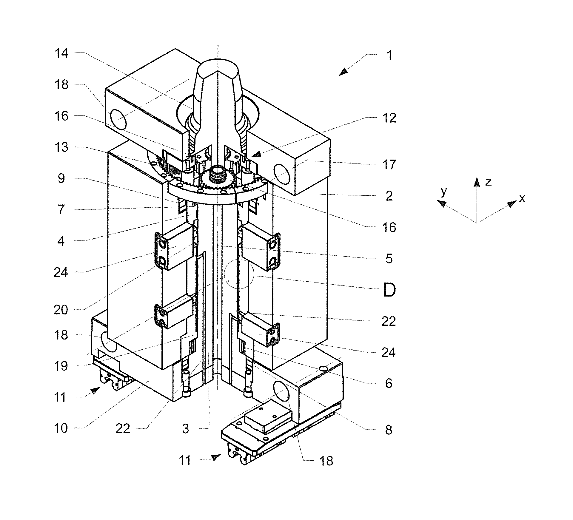
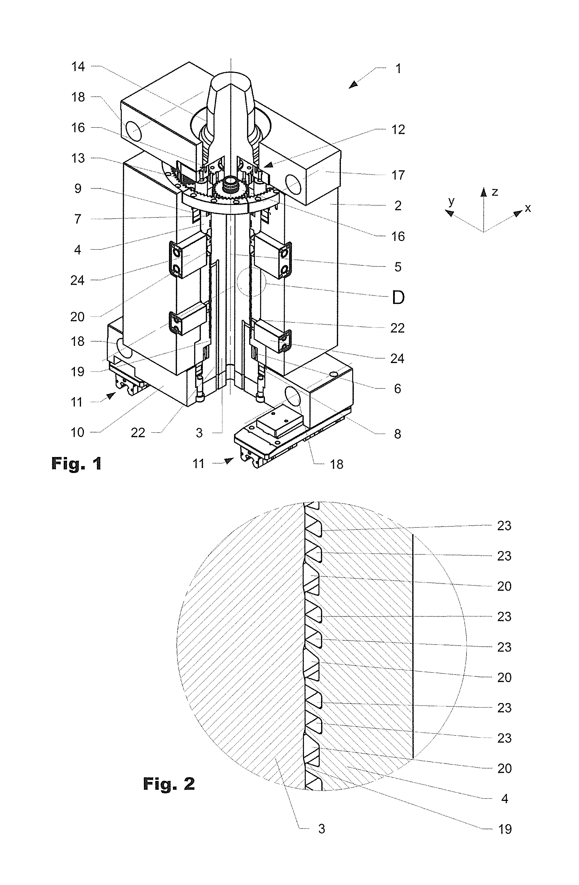
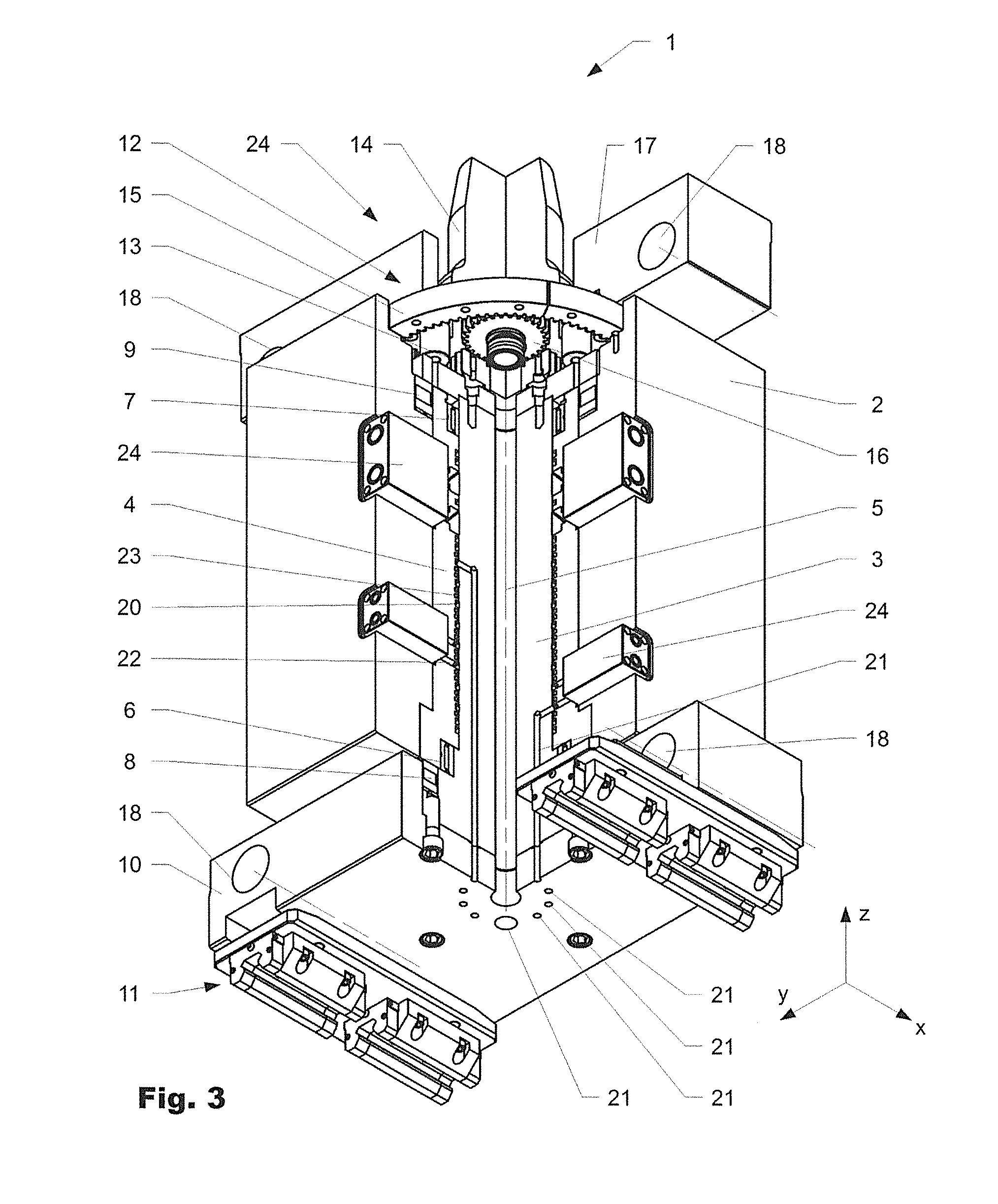
[0028]FIG. 1 shows a first embodiment of a rotation device 1 according to the invention for a center part 2 of an injection-molding machine (not shown in detail). FIG. 3 shows the same rotation device 1 from diagonally below. In both figures, the rotation device 1 is shown partially in section so that the inner workings become visible. FIG. 2 shows detail D from FIG. 1 in an enlarged representation.

[0029]The rotation device 1 has a central column 3, about which the center part 2 is rotatably mounted. In the embodiment shown, the column 3 is surrounded by a sleeve 4, which is rotatably arranged about an axis of rotation 5 with respect to the column 3.

[0030]The sleeve 4 or the center part 2 respectively is operatively connected to the column 3 by means of a first and a second radial bearing 6, 7 and a first and a second axial bearing 8, 9, which absorb forces between stationary and moving parts.

[0031]On the underside, the column 3 merges into a base 10 which is mounted with respect to...


PUM

PropertyMeasurementUnit
axis of rotationaaaaaaaaaa
electrical poweraaaaaaaaaa
structureaaaaaaaaaa

Abstract

The invention relates to a rotation device (1) for rotating the center part (2) in an injection-molding device. The rotation device comprises a column (3) which is non-rotatably mounted in the interior of the center part (2) and a sleeve (4) surrounding the same which is mounted such as to rotate with the center part (2), said sleeve (4) and said column (3) being operatively interconnected via a drive.

Description

BACKGROUND OF THE INVENTION[0001]1. Field of the Invention[0002]The present invention lies within the realm of devices for the injection molding of materials, in particular plastic parts. The invention lies particularly with the realm of injection-molding devices having a rotation device for rotating one or more center blocks in an injection-molding device according to the pre-characterizing clause of the independent patent claim.[0003]2. Discussion of Related Art[0004]Injection-molding devices for injection molding having one or more rotating center parts which are rotated by 90° or 180° about an axis are known from the prior art. These are used, for example, for the efficient production of multi-component plastic parts. At least one rotatable center part (center block) is provided between two clamping plates for first and second mold halves which can be moved along tie bars in opposite directions. The center block is preferably movably mounted on the tie bars and / or with respect t...

Claims


Application Information

Patent Timeline
Patent Type & Authority Patents(United States)
IPC IPC(8): B29C45/16B29C45/04
CPCB29C45/0441B29C45/045B29C45/1628
Inventor ARMBRUSTER, RAINER
Owner FOBOHA
Why Eureka
Try Eureka