
Oil exploration probe

a technology of oil exploration and probes, which is applied in the direction of fluid removal, drilling machines and methods, and accessories of boreholes/wells, etc., can solve the problems of high cost of transportation and installation of all the heavy drilling equipment at a site, low chances of finding oil, and inability to get this drilling equipment to the site. , to achieve the effect of cheap drilling, lowering into the ground, and strengthening and boosting the strength and security of our country and the national economy

Active Publication Date: 2015-10-27
OEP ASSOC TRUSTEE FOR OIL EXPLORATION PROBE CRT TRUST
View PDF22 Cites 21 Cited by
  • Summary
  • Abstract
  • Description
  • Claims
  • Application Information

AI Technical Summary

Benefits of technology

The oil exploration probe allows for inexpensive or expensive versions to be made for farmers and landowners to use. The device can have various functions and features depending on the needs of the user. New discoveries of oil could make farmers and landowners become wealthy and secure, and strengthen the economy and security of the country. Overall, the oil exploration probe offers a tool for lifting farmers out of poverty and allowing them to partake in the American Dream.

Problems solved by technology

The problem with trying to discover new oil is that it is very expensive to have all the heavy drilling equipment transported and set up at a site to try and drill a test hole.
Many times the uneven topography of the terrain makes it almost impossible to get this drilling equipment to the site.
Even if you do have vast amounts of money to spend on drilling a test hole, the chances of finding oil are very low.
They are unlikely to ever have enough money for a professional drilling company to come to their property and set up all the equipment to drill a test well hole.

Method used


Image

  • Oil exploration probe
  • Oil exploration probe
  • Oil exploration probe

Examples


example 1

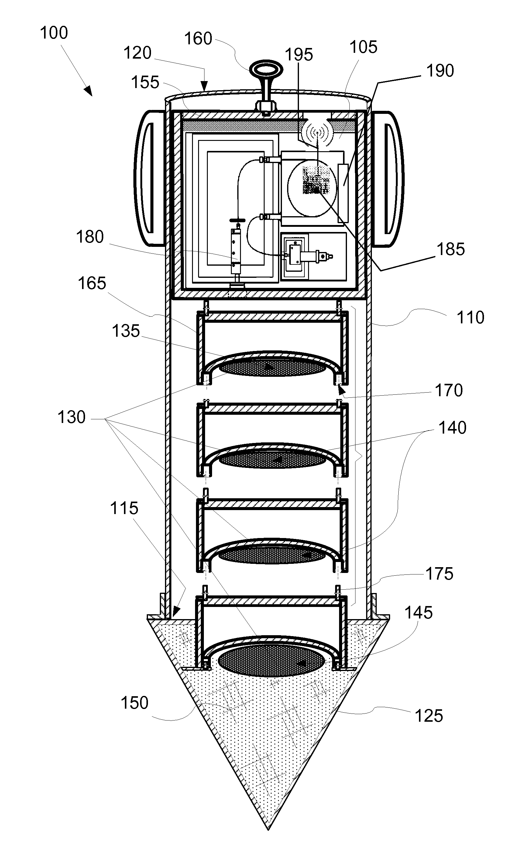
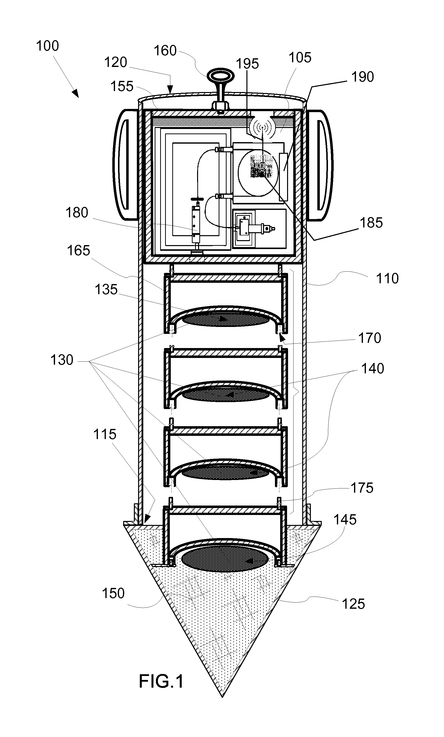
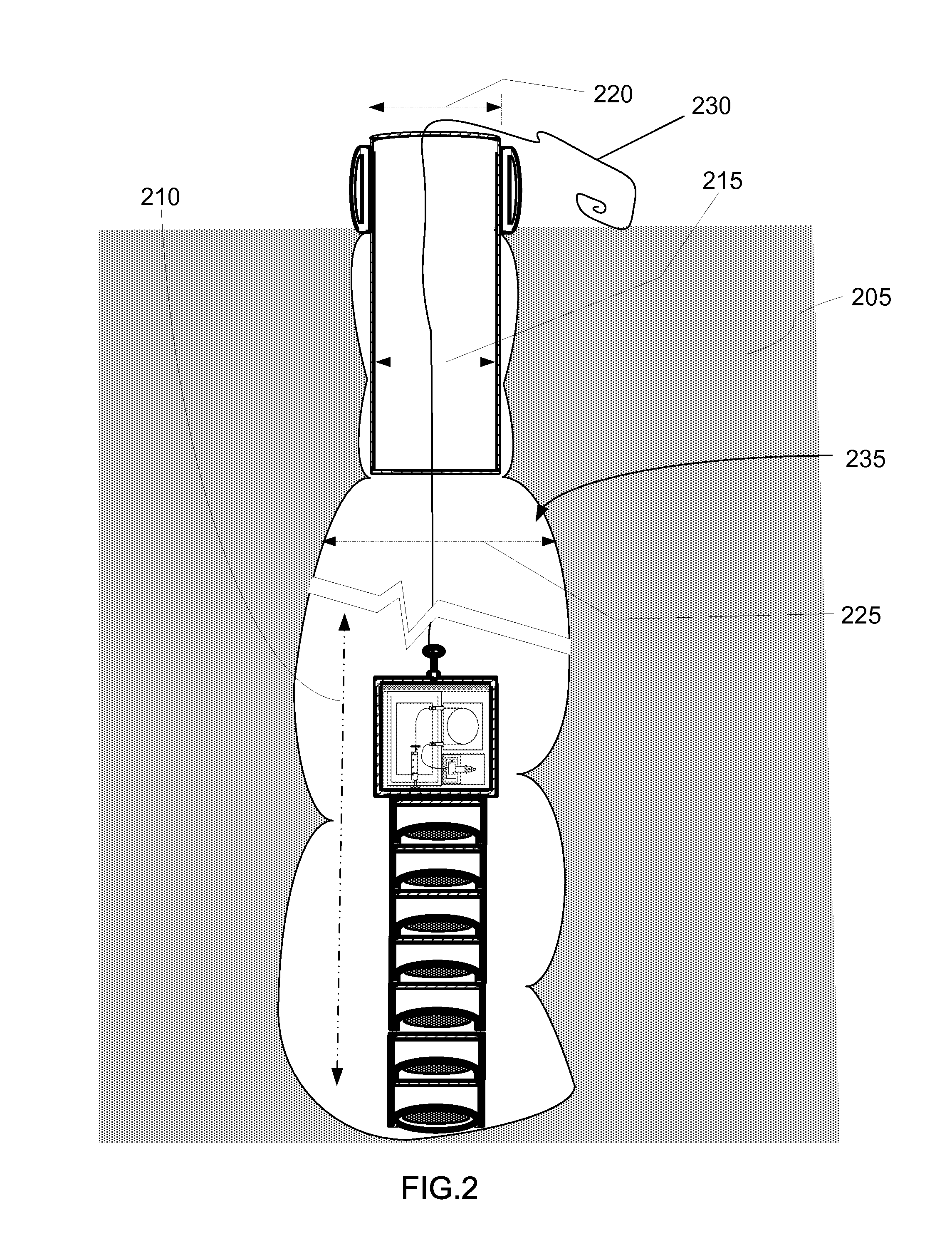
[0039]In one embodiment, an oil exploration instrument is fitted into the payload body in the metallic cylindrical casing. A stack of shaped charges is loaded below the payload body. A breakaway plastic nose cone is screwed onto the end of the casing to close up the bottom of the metallic cylindrical casing. The metallic cylindrical casing has grip handles on the side so a farmer can lift up the casing and thrust the casing and nose cone into the ground to reach a vertical starting position. When the first shaped charge module within the plastic nose at the bottom of the casing goes off, it explodes apart the plastic-like nose cone and makes a hole in the ground so that the payload body with the oil exploration instrument now has room to start sliding downward and out of the casing.

[0040]Each subsequent shaped charge that detonates causes a void below the shaped charge and allows gravity to drop the shaped charge stack lower along with the payload body and oil exploration instrument...


PUM


Abstract

An exploratory shaft-making apparatus creates a vertical hole down into a geological formation while sending a payload into the vertical hole. The apparatus includes a metallic cylindrical casing; a hollow, conical head section; a payload body; and shaped charges of high explosive below the payload body. The shaped charges are adapted to sequentially detonate starting with the bottom-most shaped charge. The detonation of each shaped charge is configured to create a void space in the geological formation below the casing. The void space permits gravity to move the remaining shaped charges and the payload body atop them to slide downward so that the next shaped charge to detonate is positioned below the bottom end of the metallic cylindrical casing. A shock absorbing material may be included in the head section. The payload body optionally has a removable cap. A lift fitting may be attached to the payload body.

Description

TECHNICAL FIELD[0001]In the field of boring or penetrating a geological formation, a means is disclosed for initially forming and radially enlarging an elongated hole in the geological formation in situ by dislocating the solid material of the geological formation.BACKGROUND ART[0002]A primary and important source of energy in the world today is oil. It is the backbone of our economy. It heats our homes, and propels our cars, trucks, ships, airplanes, and makes sure we have a job to work at. Because oil is so valuable, it represents great wealth and that is why it is referred to as black gold.[0003]Near-surface petroleum deposits are well known phenomena mostly observed by petroleum exuding or seeping from the ground. Petroleum seeps are common in many areas of the world. The occurrence of surface petroleum was often memorialized in location names associated with early oil and gas exploitation as well as scientific and technological developments. As early as 1753, the surface oil sp...

Claims


Application Information

Patent Timeline
Patent Type & Authority Patents(United States)
IPC IPC(8): E21B7/00E21B43/116
CPCE21B43/116E21B7/007E21B49/08E21B7/26
Inventor CALVERT, S. MILL
Owner OEP ASSOC TRUSTEE FOR OIL EXPLORATION PROBE CRT TRUST
Learn More