Scroll compressor having first and second oldham couplings

a compressor and coupling technology, applied in the direction of couplings, engines of arcuate-engagement type, liquid fuel engines, etc., can solve the problems of residual compressor vibration, residual unbalance, and damage to some parts of the scroll compressor

Inactive Publication Date: 2015-10-27
DANFOSS COMML COMPRESSORS
View PDF12 Cites 8 Cited by
  • Summary
  • Abstract
  • Description
  • Claims
  • Application Information

AI Technical Summary

Benefits of technology

[0011]It is an object of the present invention to provide an improved scroll compressor which can overcome the drawbacks encountered in conventional scroll compressors.
[0012]Another object of the present invention is to provide a scroll compressor which is reliable and which can be easily balanced.
[0019]Due to the transverse movements of the first and second Oldham couplings, the centers of gravity of the first and second Oldham couplings can be assimilated to a rotating mass, which can be easily balanced by a rotating counterweight attached to the drive shaft. Therefore, the compressor vibrations generated by the translation movements of the first and second Oldham couplings can be greatly reduced. Such a limitation of the compressor vibrations leads to an improvement of the compressor reliability and efficiency.
[0025]According to an embodiment of the invention, the center of the circular trajectory is substantially located on the rotation axis of the drive shaft. This arrangement of the first and second Oldham couplings allows to cancel the residual unbalance due to the first and second Oldham couplings movements, and thus to greatly improve the balance the compressor.

Problems solved by technology

However, the unbalance induced by the reciprocating translation movement of the Oldham coupling cannot be perfectly compensated thanks to a rotating counterweight, which leads to the presence of a residual unbalance, and thus of residual compressor vibrations.
Such residual compressor vibrations may cause a damage of some parts of the scroll compressor, and may detract the efficiency of the scroll compressor.

Method used


Image

  • Scroll compressor having first and second oldham couplings
  • Scroll compressor having first and second oldham couplings
  • Scroll compressor having first and second oldham couplings

Examples


Embodiment Construction

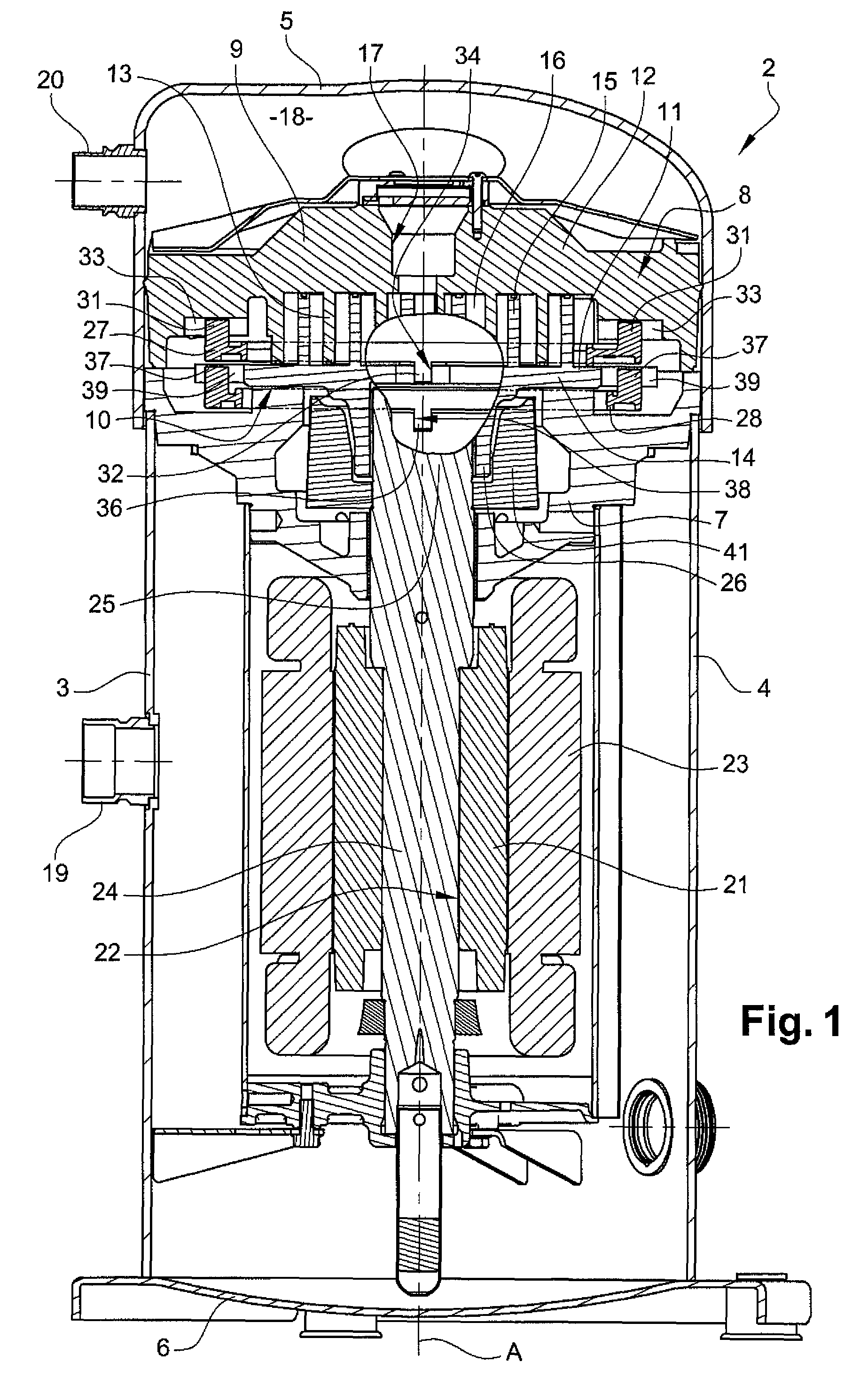
[0076]FIG. 1 shows a scroll refrigeration compressor 2 occupying a vertical position. However, the scroll refrigeration compressor 2 according to the invention could occupy an inclined position, or a horizontal position, without significant modification to its structure.

[0077]The scroll refrigeration compressor 2 shown in FIG. 1 comprises a closed housing 3 defined by a shell 4 whose top and bottom ends are respectively closed by cap 5 and a base 6.

[0078]The scroll refrigeration compressor 2 also comprises a support frame 7 fixed in the closed housing 3, the closed casing 3 and the support frame 7 defining a low pressure volume.

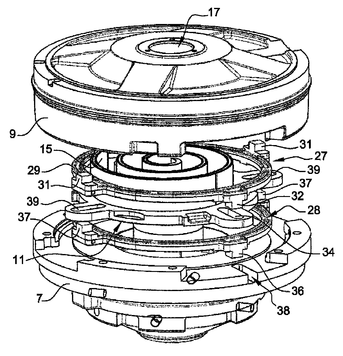
[0079]The scroll refrigeration compressor 2 further comprises a scroll compression unit 8 disposed above the support frame 7. The scroll compression unit 8 has a fixed scroll member 9 and an orbiting scroll arrangement 10. In particular the fixed scroll member 9 is fixed in relation to the closed housing 3, and the orbiting scroll arrangement 10 includes an o...


PUM


Abstract

This scroll compressor includes a first fixed scroll member, an orbiting scroll arrangement including a first orbiting scroll member, a first Oldham coupling provided between the first orbiting scroll member and the first fixed scroll member and configured to prevent rotation of the first orbiting scroll member with respect to the first fixed scroll member, a fixed element opposite to the first fixed scroll member with respect to the orbiting scroll arrangement, and a second Oldham coupling provided between the orbiting scroll arrangement and the fixed element and configured to prevent rotation of the orbiting scroll arrangement with respect to the fixed element. The first Oldham coupling is slidable with respect to the first fixed scroll member along a first displacement direction, and the second Oldham coupling is slidable with respect to the fixed element along a second displacement direction transverse to the first displacement direction.

Description

FIELD OF THE INVENTION[0001]The present invention relates to a scroll compressor, and in particular to a scroll refrigeration compressor.BACKGROUND OF THE INVENTION[0002]As known, a scroll compressor comprises:[0003]a fixed scroll member comprising a fixed end plate and a fixed spiral wrap provided on one face of the fixed end plate,[0004]an orbiting scroll member comprising an orbiting end plate and an orbiting spiral wrap provided on one face of the orbiting end plate, the fixed spiral wrap and the orbiting spiral wrap forming a plurality of compression chambers,[0005]a support frame, also named crankcase, on which is slidably mounted the orbiting end plate of the orbiting scroll member,[0006]an Oldham coupling provided between the orbiting scroll member and the support frame, and configured to prevent rotation of the orbiting scroll member with respect to the support frame, the Oldham coupling being slidably mounted with respect to the support frame along a first displacement dir...

Claims


Application Information

Patent Timeline
Patent Type & Authority Patents(United States)
IPC IPC(8): F16D3/04F04C29/00F04C18/02F01C1/02
CPCF04C29/0057F04C18/0207F04C18/0215F04C29/0021
Inventor BONNEFOI, PATRICEROSSON, YVESCLAUDIN, INGRID
Owner DANFOSS COMML COMPRESSORS
Why Eureka
Try Eureka