Shackle assembly with pin and retaining ring

a technology of pin and retaining ring, which is applied in the direction of chain fastenings, shackles, etc., can solve the problems of retaining or securing the pin to these devices with questionable integrity, and the above-mentioned devices have been used,

Active Publication Date: 2015-10-27
PURE SAFETY GRP INC
View PDF18 Cites 3 Cited by
  • Summary
  • Abstract
  • Description
  • Claims
  • Application Information

AI Technical Summary

Benefits of technology

[0008]It is an object of the present invention to provide a shackle assembly that reinforces safety.
[0009]It is another object of the present invention to provide improved performance over existing connectors.
[0010]It is another object of the present invention to provide a shackle assembly that reduces operating costs.
[0011]It is another object of the present invention to improve the reliability of shackle connectors.
[0018]In another aspect of the present invention, a shackle assembly kit includes the body, pin, and retaining ring(s) as components to be assembled. The kit also includes instructions for installing the annular retaining ring(s) in the annular recess and advancing the pin through the first opening and into the second opening with the annular retaining ring seating in the annular groove, thereby preventing the pin from being removed from the body.

Problems solved by technology

The above-mentioned devices have been used for years, but remain bulky for use with small hand-held objects such as hand tools.
Additionally, retaining or securing the pin to these devices is often done with questionable integrity.
For example, a locking nylon insert of a lock nut may become worn or otherwise fail to lock the nut in place, thereby allowing the nut to loosen and fall off.
A split sleeve used over pins in hammerlock shackles may similarly catch on objects along the split, thereby damaging or opening the sleeve to allow the hammerlock link to open.
Further, a split sleeve is difficult to install without proper tools designed for such installation.
In some cases, failure of the device is a minor inconvenience.
In other cases, a shackle failure can waste valuable time and resources, cause injury and damage due to the separating links, increase operating costs by necessitating replacement parts and repairs, and introduce foreign material to industrial systems that contaminates a system or requires shut down of the system to retrieve the foreign object.

Method used


Image

  • Shackle assembly with pin and retaining ring
  • Shackle assembly with pin and retaining ring
  • Shackle assembly with pin and retaining ring

Examples


Embodiment Construction

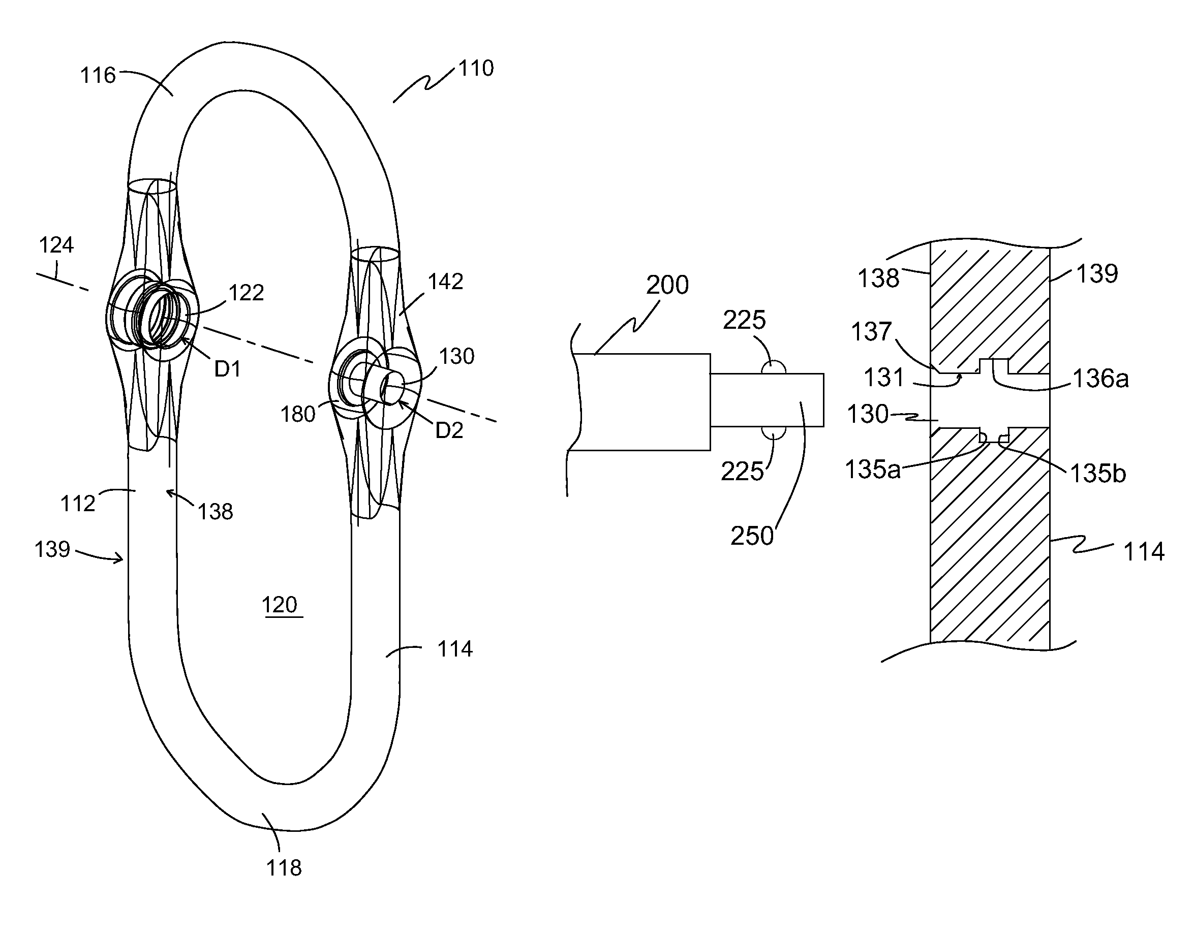
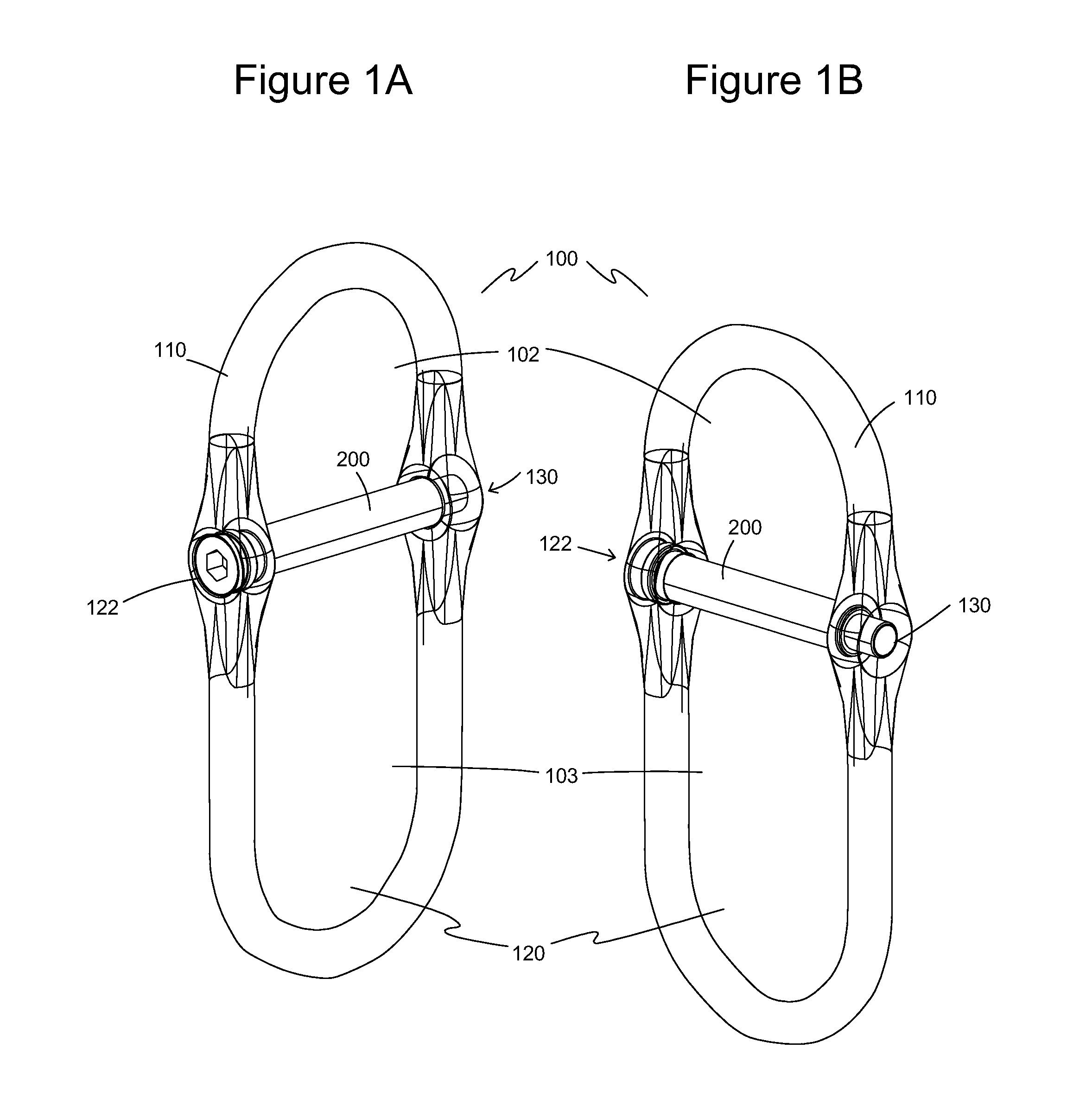
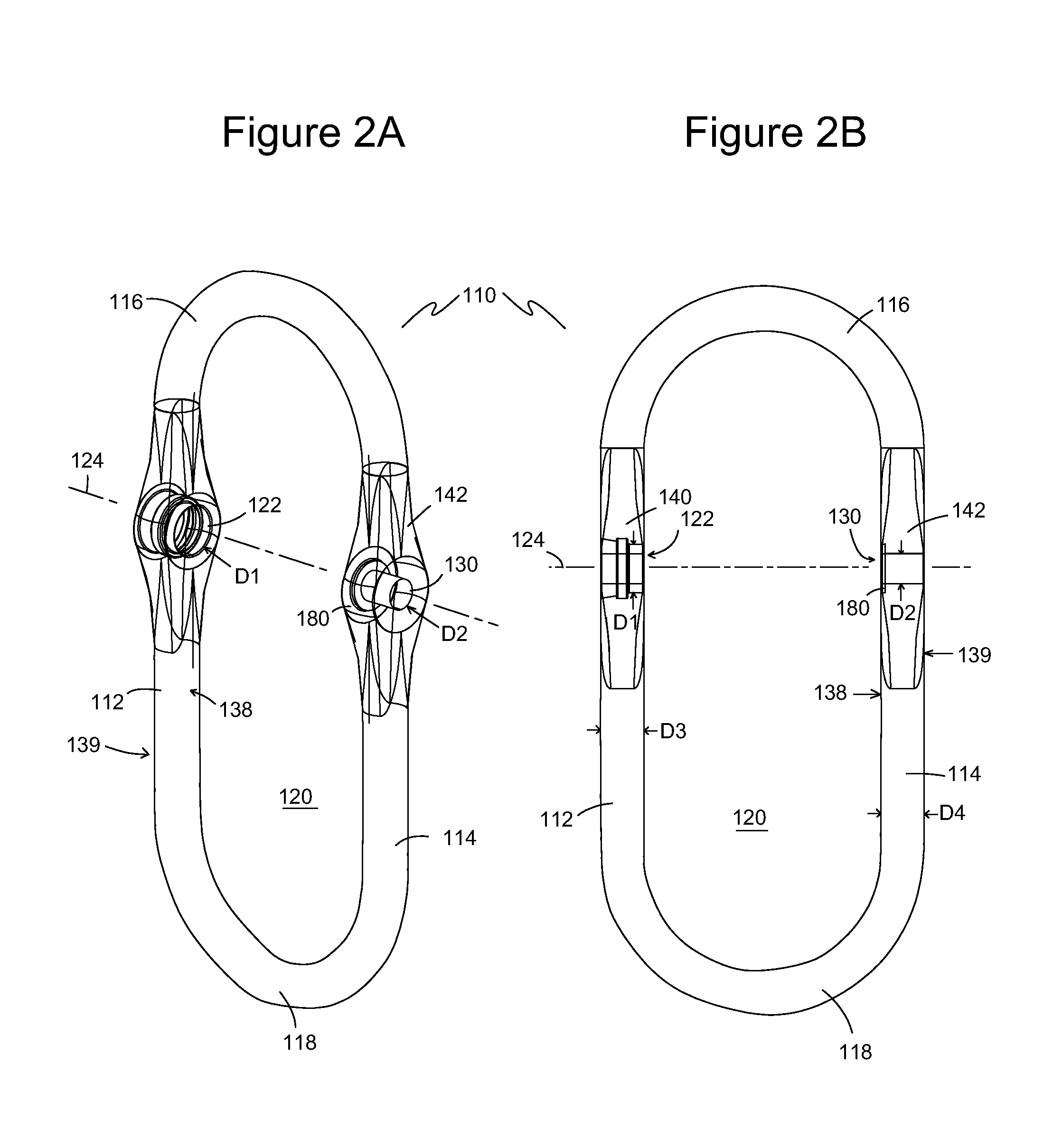
[0038]Embodiments of a shackle assembly 100 of the present invention are illustrated in FIGS. 1-13. FIGS. 1A and 1B illustrate front perspective and rear perspective views, respectively, of one embodiment of a shackle assembly 100 having a body 110 and a pin 200. Body 110 in this embodiment defines a closed geometry with a “racetrack” shape. In other embodiments, the closed geometry is an oval, circle, rectangle, square, trapezoid, irregular shape, or any other closed geometry. Pin 200 extends transversely through a first pin opening 122 and a second pin opening 130 that are axially aligned and extend through or into body 110. Pin 200 divides a primary opening 120 defined by the closed geometry into a first opening 102 and a second opening 103. As discussed below, pin 200 is retained in body 110 by a retaining ring 290 (shown for example in FIG. 11).

[0039]Referring now to FIGS. 2A and 2B, a front perspective view and a front elevational view, respectively, illustrate body 110 as sho...


PUM


Abstract

A shackle assembly has a body that includes a first side member with a first side aperture, a second side member with a second side aperture, and at least one end portion extending between and connecting the first side member and the second side member. At least one of the apertures defines an annular recess. A pin has a first end portion received in the first side aperture, a second end portion received in the second side aperture, and a pin body extending between the first end portion and the second end portion. At least one end portion of the pin defines an annular groove corresponding to the annular recess(es). A retaining ring with a pair of open ends is seated in the annular groove and extends radially into the corresponding annular recess, thereby preventing the pin from being removed from the body.

Description

BACKGROUND OF THE INVENTION[0001]1. Field of the Invention[0002]The present invention relates generally to hand tools and connectors. More particularly, the present invention relates to shackle-type connectors.[0003]2. Description of the Prior Art[0004]Traditionally, a shackle has a U-shaped metal bracket (also known as a clevis) with two arms. The ends of the two arms span an opening between them, which is closed with a bolt or clevis pin inserted through openings in the ends of the arms. Shackles are commonly used to connect multiple items together or secure items to a chain or rope. In some cases, the user loops one end of a strap around the clevis or clevis pin with the other end of the strap being secured to a fixed object. Similar to a bolt, one end of the clevis pin often has an enlarged head or cap that prevents the pin from passing completely through openings in the clevis arms. The opposite end of the clevis pin has a hole passing transversely through the pin's end. A clev...

Claims


Application Information

Patent Timeline
Patent Type & Authority Patents(United States)
IPC IPC(8): F16G15/02F16G15/04F16G15/06
CPCF16G15/06F16G15/04F16G15/02
Inventor MOREAU, DARRELL A.MOREAU, ANDRE W.
Owner PURE SAFETY GRP INC
Why Eureka
Try Eureka