Storage hot water supplying apparatus, hot water supplying and space heating apparatus, operation control apparatus, operation control method, and operation control program

a technology for hot water supply and storage tanks, which is applied in the direction of domestic hot water supply systems, lighting and heating apparatus, heating types, etc. it can solve the problems of deterioration in the efficiency of actual apparatus operation, inefficient operation of conventional storage hot water supply apparatuses, and loss of high-temperature water stored in water storage tanks. , to achieve the effect of efficient heating water, efficient operation and increased efficiency

Active Publication Date: 2015-10-27
PANASONIC INTELLECTUAL PROPERTY MANAGEMENT CO LTD
View PDF47 Cites 7 Cited by
  • Summary
  • Abstract
  • Description
  • Claims
  • Application Information

AI Technical Summary

Benefits of technology

[0016]High-temperature water stored in the water storage tank loses more heat with time. When the high-temperature water in the water storage tank is consumed for handling a load such as hot water supply, space heating, or bathwater reheating, lower-temperature makeup water is supplied to the water storage tank, or water cooled down to a lower temperature due to heat consumption is returned to the water storage tank. Such operations generate middle-temperature water, thus reducing the amount of heat stored in the water storage tank.
[0020]The present invention, conceived to address the problem; has an object of providing a storage hot water supplying apparatus which efficiently operates with a large increase in available heat in the water storage tank.
[0022]In the aspect of the present invention, a water outlet is selected based on the provision temperature and the temperature to be taken out through the water outlets, and the water taken out through the selected water outlet is heated. Here, the provision temperature is a temperature of water to be provided to the load portion, that is, a temperature of water which can be effectively used for handling a load. For example, water having a temperature lower than the provision temperature is water not usable for handling a load is. The water stored in the water storage tank but not usable for handling a load due to its temperature is taken out through the water outlet selected based on the provision temperature, and then heated. This suppresses increase in the amount of water which is in the water storage tank but is not usable for handling the load due to its inappropriate temperature, and produces a large increase in available heat, thereby allowing the storage hot water supplying apparatus to efficiently operate.
[0024]In this aspect of the present invention, the water outlet selected from among the water outlets allows taking out of the water having a temperature lower than and closest to the provision temperature. Such selection of a water outlet is efficiently made through a simple comparison. This suppresses increase in the amount of water not usable for handling the load due to its inappropriate temperature in the water storage tank, and produces a large increase in available heat in the water storage tank, thereby allowing the storage hot water supplying apparatus to efficiently operate.
[0026]In this aspect of the present invention, the COPs are calculated based on an assumption that an amount of available heat of the water is zero in the case where the water has a temperature lower than the provision temperature, and the water outlets which provides the largest COP among is selected. That is, the COPs are calculated based on an assumption that an amount of heat of the water not usable for handling a load is zero. Thus, a water outlet which provides the highest efficiency is selected in accordance with properties of a heat pump, thereby increasing the available heat in the water storage tank at maximum efficiency.
[0028]According to the present invention, a storage hot water supplying apparatus which efficiently operates is provided. The storage hot water supplying apparatus operates with efficiency increased against a load (efficiency of an apparatus in actual operation) by efficiently heating water which is in a water storage tank but cannot be effectively used and producing a large increase in available heat in the water storage tank.

Problems solved by technology

However, there is a problem that the conventional storage hot water supplying apparatuses operate inefficiently in a manner described as follows.
High-temperature water stored in the water storage tank loses more heat with time.
Therefore, wasteful heating, excessive heating, or inefficient heating of medium-temperature water leads to deterioration in the efficiency of an actual apparatus in operation.

Method used


Image

  • Storage hot water supplying apparatus, hot water supplying and space heating apparatus, operation control apparatus, operation control method, and operation control program
  • Storage hot water supplying apparatus, hot water supplying and space heating apparatus, operation control apparatus, operation control method, and operation control program
  • Storage hot water supplying apparatus, hot water supplying and space heating apparatus, operation control apparatus, operation control method, and operation control program

Examples


embodiment 1

[0042]The following describes a storage hot water supplying apparatus according to Embodiment 1 of the present invention with reference to the drawings.

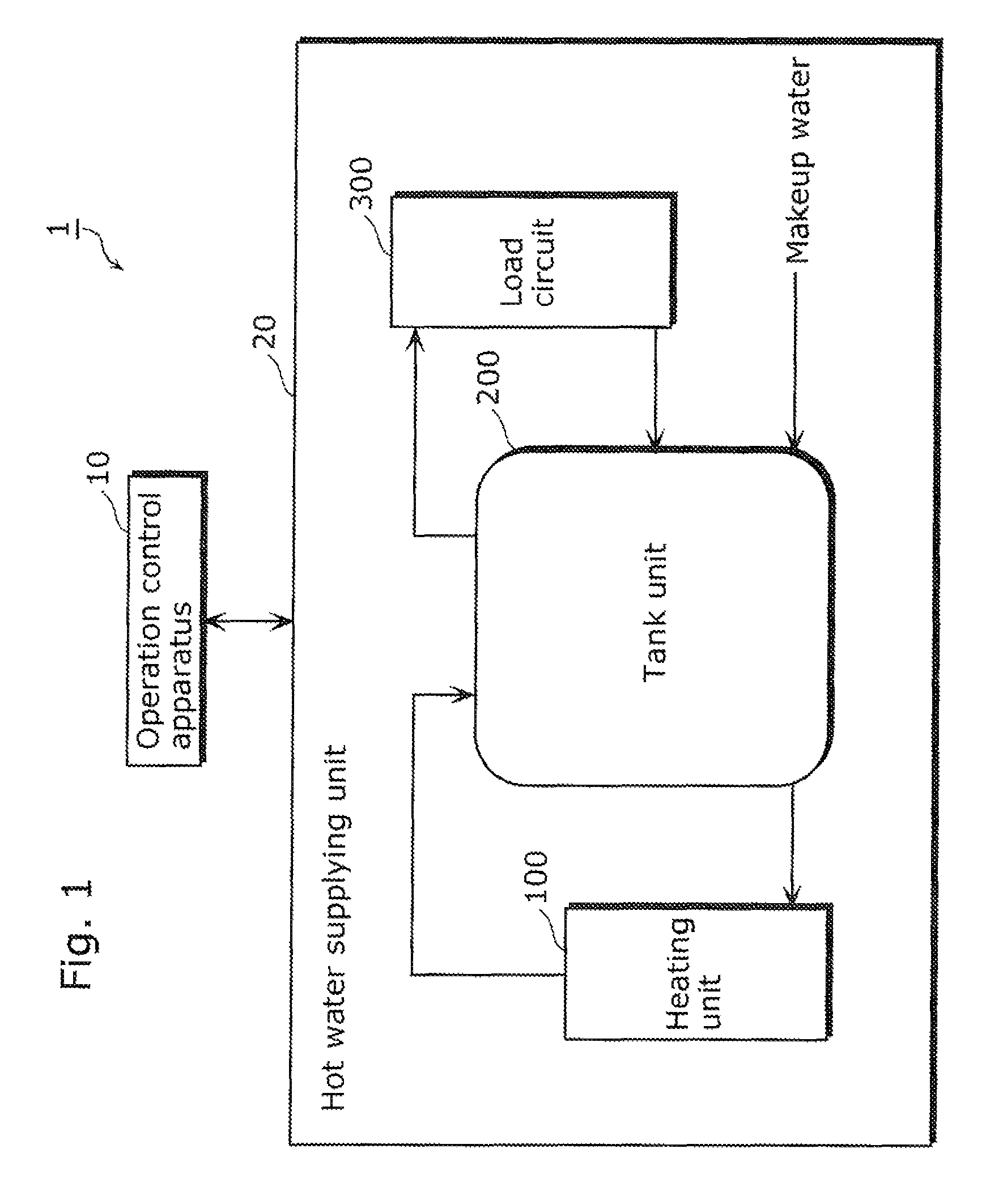
[0043]FIG. 1 is a schematic view illustrating a storage hot water supplying apparatus 1 according to Embodiment 1 of the present invention.

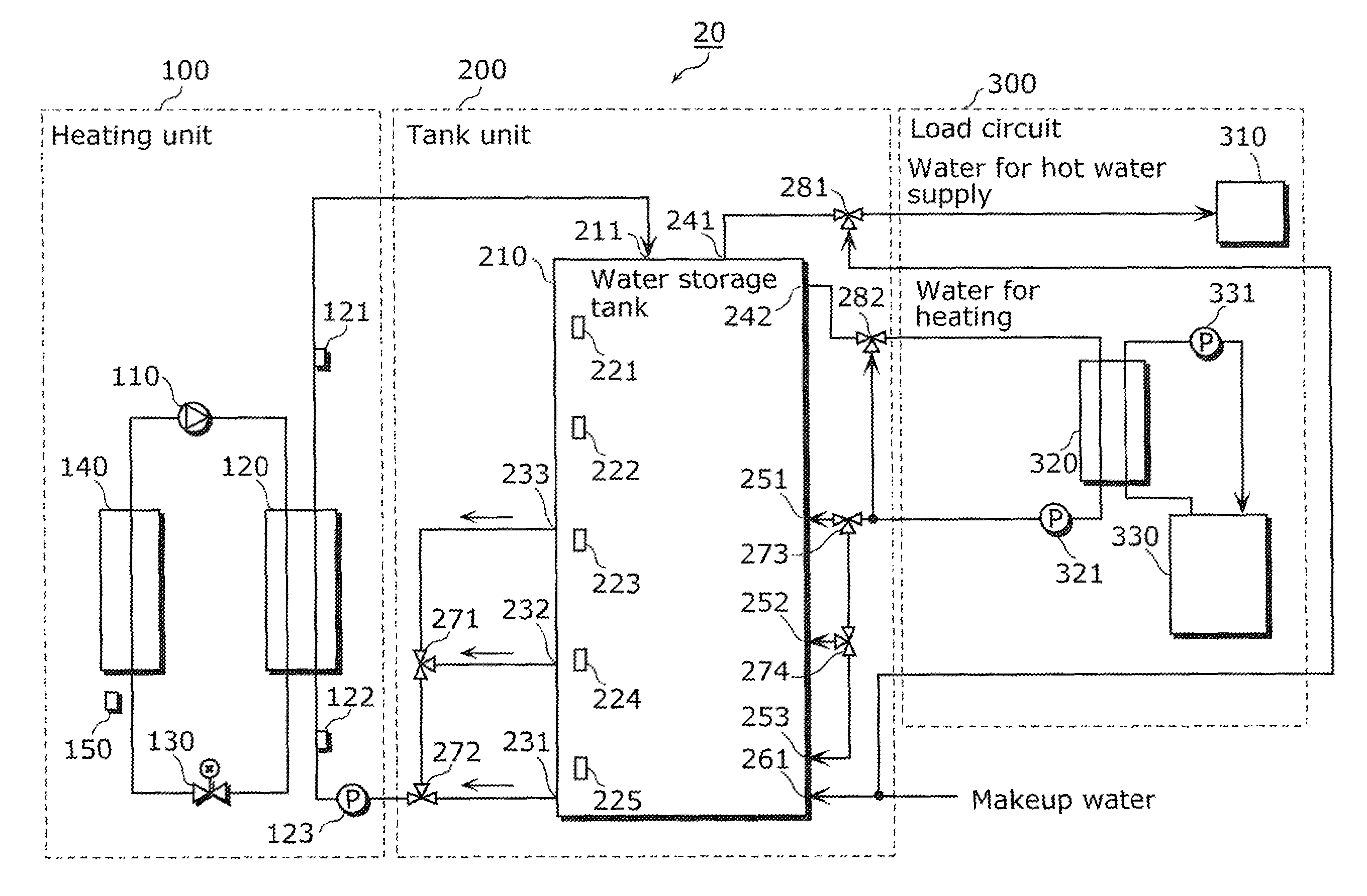
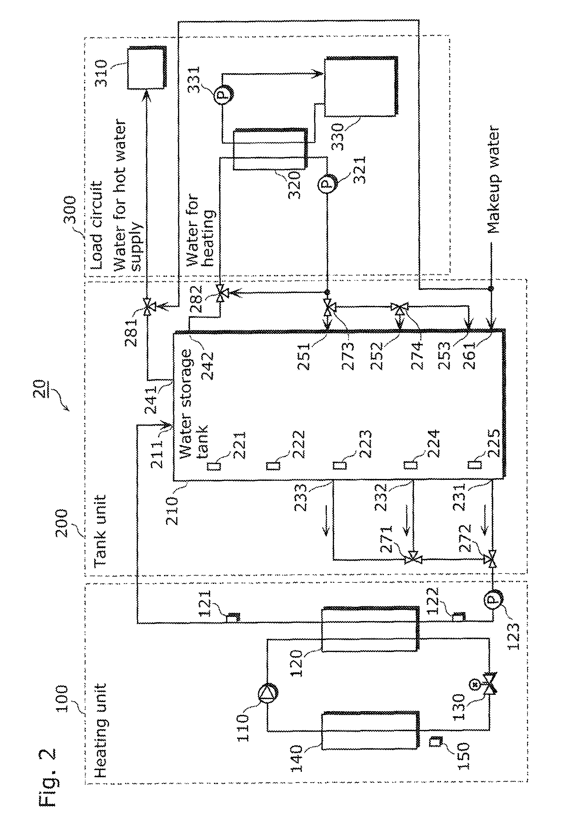
[0044]The storage hot water supplying apparatus 1 is an apparatus which supplies hot water for use by users. As shown in FIG. 1, the storage hot water supplying apparatus 1 includes an operation control apparatus 10 and a hot water supplying unit 20.

[0045]The operation control apparatus 10 controls operation of the storage hot water supplying apparatus 1. Specifically, the operation control apparatus 10 controls operation of the storage hot water supplying apparatus 1 to allow the storage hot water supplying apparatus 1 to efficiently operate with largely increased available heat in a water storage tank. The operation control apparatus 10 will be described in detail later.

[0046]Under the control b...

embodiment 2

[0143]The following describes a storage hot water supplying apparatus according to Embodiment 2 of the present invention.

[0144]In Embodiment 1, an outlet for water to be heated through which water having a temperature lower than and closest to the provision temperature is taken out is selected from among the outlets for water to be heated 1 to 3. On the other hand, in Embodiment 2, an outlet for water to be heated which provides the largest actual COP among the outlets for water to be heated 1 to 3 is selected based on calculated actual COPs.

[0145]Here, it is a property of a heat pump that performance of a heat pump depends on outside air temperature, entering water temperature, and target temperature.

[0146]FIG. 9 shows COPs with respect to entering water temperatures against outside air temperatures. Specifically, FIG. 9 shows a graph having a horizontal axis which represents temperatures of the water entering the heating unit 100 (entering water temperatures), and a vertical axis ...


PUM


Abstract

A storage hot water supplying apparatus provides heated water to a load circuit through which users uses water, and includes a water storage tank which stores water and has outlets for water to be heated at different heights, and an outlet selecting unit to select, from among the outlets, an outlet to take out the water, based on a provision temperature which is a temperature of water to be provided from the water storage tank to the load circuit and temperatures of the water to be taken out through the outlets. A heating unit heats the water taken out through the selected outlet and to be returned to the water storage tank.

Description

BACKGROUND OF INVENTION[0001]1. Technical Field[0002]The present invention relates to a storage hot water supplying apparatus which heats water in a water storage tank and supplies hot water using the heated water stored in the water storage tank.[0003]2. Background Art[0004]When heating water in the water storage tank, a conventional storage hot water supplying apparatus transmits low-temperature water in a lower part of the water storage tank using a heating unit pump through an outlet to a heating unit, such as a heat pump, heats the low-temperature water to a high temperature using the heating unit, and provides the high-temperature water to an upper part of the water storage tank, so that temperature of the water in the water storage tank is raised to a high-temperature gradually from the water in the upper part, and eventually the whole of the storage tank.[0005]The high-temperature water stored in the water storage tank is used for hot water supply, space heating, bathwater r...

Claims


Application Information

Patent Timeline
Patent Type & Authority Patents(United States)
IPC IPC(8): F24H1/18E03B1/00F24H4/04F24D3/08F24D19/10F24H9/20
CPCF24H4/04F24D3/082F24D19/1069F24D19/1072F24H9/2007F24D2220/042F24D2220/06Y10T137/0318Y10T137/6416F24D2240/26F24D2240/12F24D17/02F24H15/258F24H15/385F24H15/457F24H15/225F24H15/38F24H15/281F24H15/219F24H15/215
Inventor NAGATA, EIKOHAYASHIDA, GAKU
Owner PANASONIC INTELLECTUAL PROPERTY MANAGEMENT CO LTD
Why Eureka
Try Eureka