Connector

a technology of connecting rods and connectors, applied in the direction of incorrect coupling prevention, coupling device connection, coupling contact members, etc., can solve the problems of preventing an increase in and it is difficult to employ the connector for large-current devices, so as to achieve easy elastic deformation, increase the cross-sectional area of the movable portion, and increase the allowable current of the terminal

Active Publication Date: 2015-11-03
IRISO ELECTRONICS CO LTD
View PDF9 Cites 20 Cited by
  • Summary
  • Abstract
  • Description
  • Claims
  • Application Information

AI Technical Summary

Benefits of technology

[0009]In the connector unit configured as above, the movable portion of the first terminal of the first connector can easily be elastically deformed in the front-back direction or up-down direction of the connector, since the movable portion is larger in the width direction than in the thickness direction. Likewise, the movable portion of the second terminal of the second connector can easily be elastically deformed in the width direction of the connector, since the movable portion is larger in the thickness direction than in the width direction. Therefore, when the positional shift between the substrates takes place in the front-back direction of the connector the movable portion of the first terminal is elastically deformed, and when the positional shift between the substrates takes place in the width direction of the connector the movable portion of the second terminal is elastically deformed.
[0010]Forming thus the movable portion of the first terminal of the first connector to be larger in the width direction than in the thickness direction, so as to be elastically deformed in the front-back direction of the connector, and the movable portion of the second terminal of the second connector to be larger in the thickness direction than in the width direction, so as to be elastically deformed in the width direction of the connector, allows the respective movable portions of the first and second terminals to be formed with an increased cross-sectional area, thereby enabling the allowable current of the terminal to be increased, unlike a configuration in which the movable portion is elastically deformable to a sufficient extent both in the front-back direction and in the width direction of the connector.
[0012]The movable portion of the terminal configured as above has a thickness taken in the front-back direction or up-down direction of the connector larger than a width taken in the width direction of the connector, and is hence easy to elastically deform in the width direction of the connector. Accordingly, the cross-sectional area of the movable portion can be increased, so that the allowable current of the terminal can be increased. In addition, the terminal includes the first and second contact portions to be brought into contact with the terminal of the other connector, with a spacing defined between the first and the second contact portion in the direction in which the connectors are fitted together. With the mentioned configuration, when the connector is fitted to the other connector the second contact portion can make contact with the terminal of the other connector following up the sliding track of the first contact portion marked thereon, and therefore even though a foreign matter is stuck to the terminal of the other connector, the second contact portion can make contact therewith after the foreign matter is removed by the first contact portion, which leads to upgraded connection reliability of the connectors.
[0013]Further, the terminal contacts the mating terminal via the first and second contact portions, and hence exerts a larger contact force on the mating terminal to firmly hold the same, compared with the case of contacting via a single contact portion. Therefore, even though the connectors are subjected to vibration during the practical use, the first and second contact portions can be prevented from micro-sliding relative to the mating terminal and from thus scraping off the plating and increasing the contact resistance. In this aspect also, the connection reliability of the connectors can be upgraded.
[0014]The connectors configured as above enable the allowable current of the terminal to be increased, despite the connectors being configured to move relative to each other in the front-back direction and the width direction thereof, and are therefore applicable to large-current devices.

Problems solved by technology

Such a configuration impedes an increase in allowable current of the terminal, thus making it difficult to employ the connector for large-current devices.

Method used


Image

  • Connector
  • Connector
  • Connector

Examples


Embodiment Construction

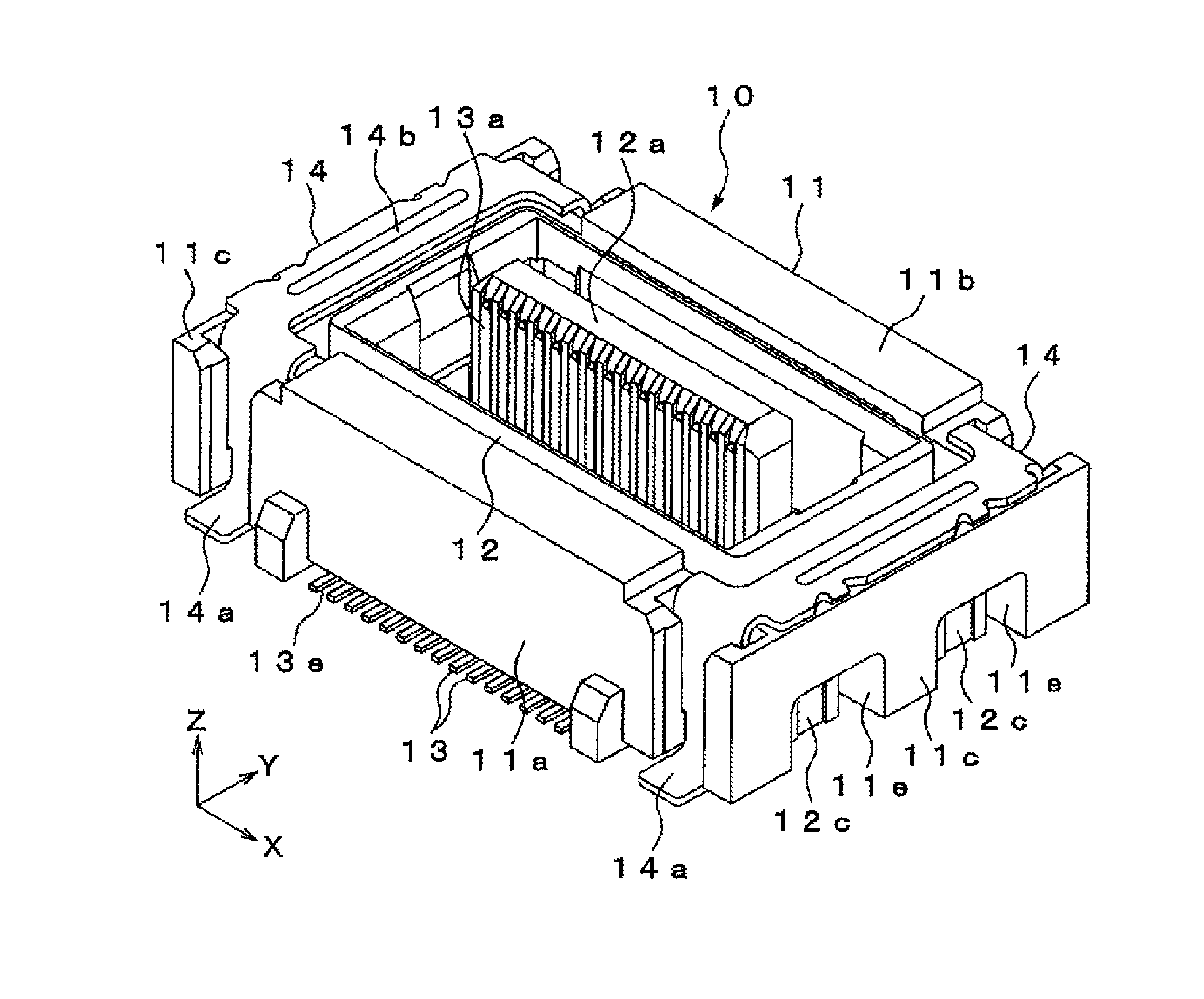
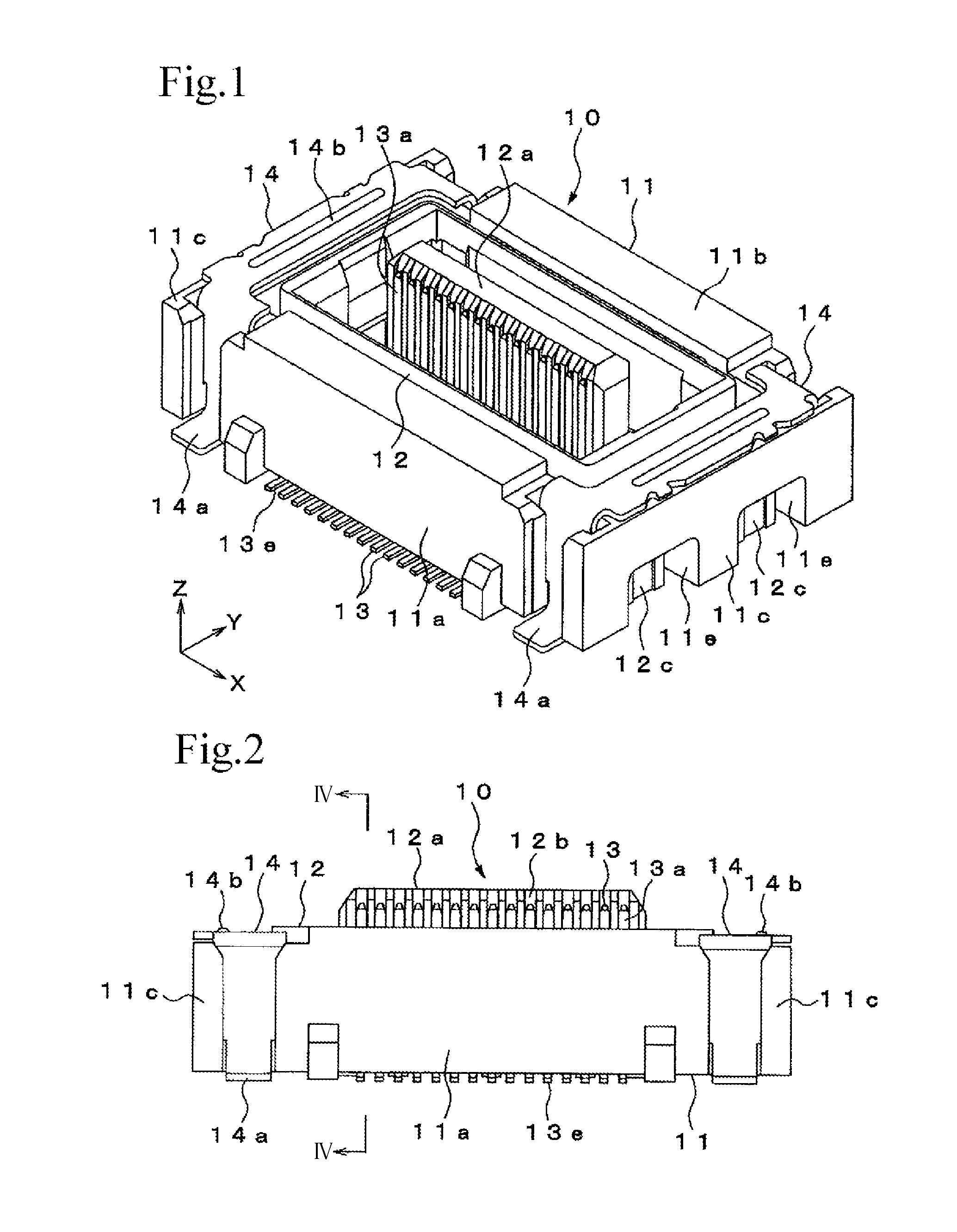
[0031]FIG. 1 through FIG. 16 illustrate a connector unit according to an embodiment of the present invention, used for connecting, for example, a pair of printed substrates to each other. In the drawings, X-direction represents a width direction of the connector, Y-direction represents a front-back direction of the connector, and Z-direction represents an up-down direction of the connector.

[0032]The connector unit according to this embodiment includes a first connector 10 to be attached to a substrate 1 of the pair of substrates 1, 2 disposed such that respective surfaces oppose each other, and a second connector 20 to be attached to the other substrate 2.

[0033]Here, although the second connector 20 is turned upside down in FIG. 15 and FIG. 16 with respect to FIG. 7 to FIG. 12, the up-down direction referred to in the following description will be based on the up-down direction in FIG. 7 to FIG. 12.

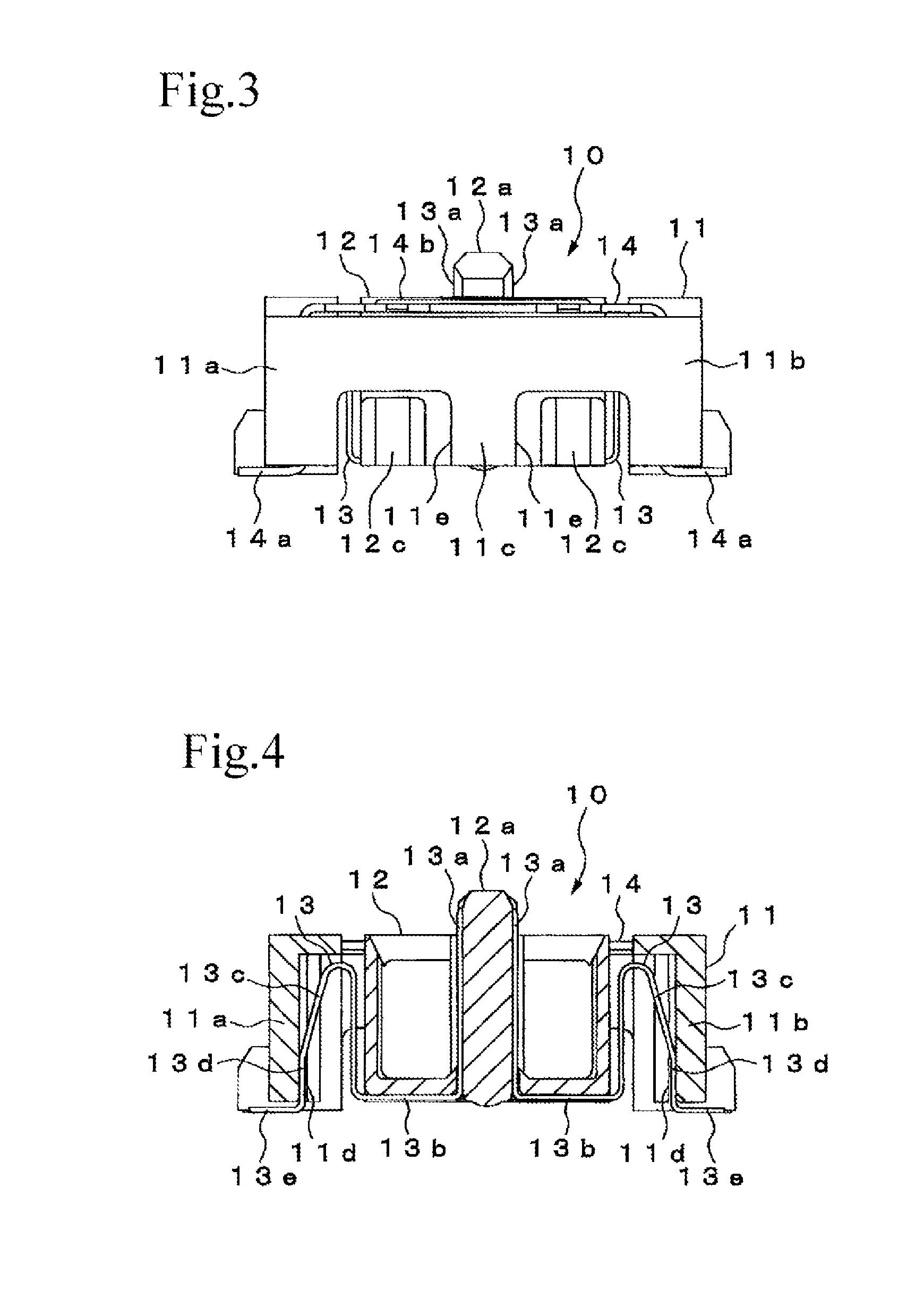
Configuration of First Connector 10

[0034]The first connector 10 includes a first fixe...


PUM


Abstract

The movable portion of the first terminal of the first connector is formed to be larger in the width direction than in the thickness direction, so as to be elastically deformed in the front-back direction of the connector, and the movable portion of the second terminal of the second connector is formed to be larger in the thickness direction than in the width direction, so as to be elastically deformed in the width direction of the connector. Therefore, the movable portions can be formed with an increased cross-sectional area, thereby enabling the allowable current of the terminals to be increased, unlike a configuration in which the movable portion is elastically deformable to a sufficient extent both in the front-back direction and in the width direction of the connector.

Description

BACKGROUND OF THE INVENTION[0001]1. Field of the Invention[0002]The present invention relates to a connector used for connecting, for example, a pair of printed substrates to each other.[0003]2. Description of the Related Art[0004]Connector units are thus far known that include a first connector attached to one of a pair of substrates disposed such that respective surfaces oppose each other, and a second connector attached to the other substrate, the first connector and the second connector being configured to be fitted together to connect the substrates, for example as disclosed in Japanese Unexamined Patent Application Publication No. 2007-18785.[0005]One of the connectors includes a fixed housing to be fixed to the substrate, a movable housing disposed to move relative to the fixed housing in a front-back direction and a width direction of the connector, and a plurality of terminals each having an end portion retained by the movable housing and the other end portion retained by t...

Claims


Application Information

Patent Timeline
Patent Type & Authority Patents(United States)
IPC IPC(8): H01R13/64H01R12/91H01R13/46H01R12/71H01R13/20H01R13/631H01R35/02
CPCH01R35/02H01R12/716H01R12/91H01R13/20H01R13/46H01R13/6315H01R12/73
Inventor FUNAYAMA, DAISUKEMITSUZUKA, SHIGERUYAMAGUCHI, TOMISABURO
Owner IRISO ELECTRONICS CO LTD
Why Eureka
Try Eureka