Reflecting device for illuminating

A reflection device and reflector technology, applied in lighting devices, fixed lighting devices, lighting applications, etc., can solve problems such as high outgoing light, failure to form, scratches, etc., and achieve less reflected scattered light, good productivity, and high flexibility sexual effect

Inactive Publication Date: 2003-05-28
DUPONT TORAY CO LTD +1
View PDF3 Cites 10 Cited by
  • Summary
  • Abstract
  • Description
  • Claims
  • Application Information

AI Technical Summary

Problems solved by technology

According to this technology, the light weight and productivity of the reflector can be improved, but the concave surface as the reflective surface is formed by mold molding, so the surface of the finished product will be transferred with the fine unevenness of the metal mold, and will rub against the molding mold. Scratching occurs, making it impossible to form a smooth reflective surface
Therefo

Method used


Image

  • Reflecting device for illuminating
  • Reflecting device for illuminating
  • Reflecting device for illuminating

Examples


Embodiment Construction

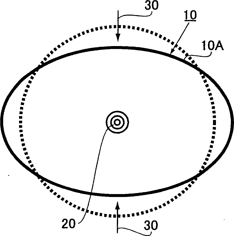
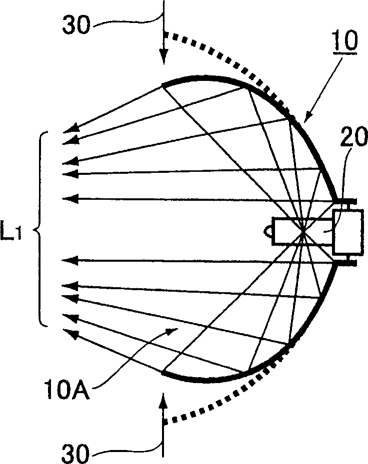
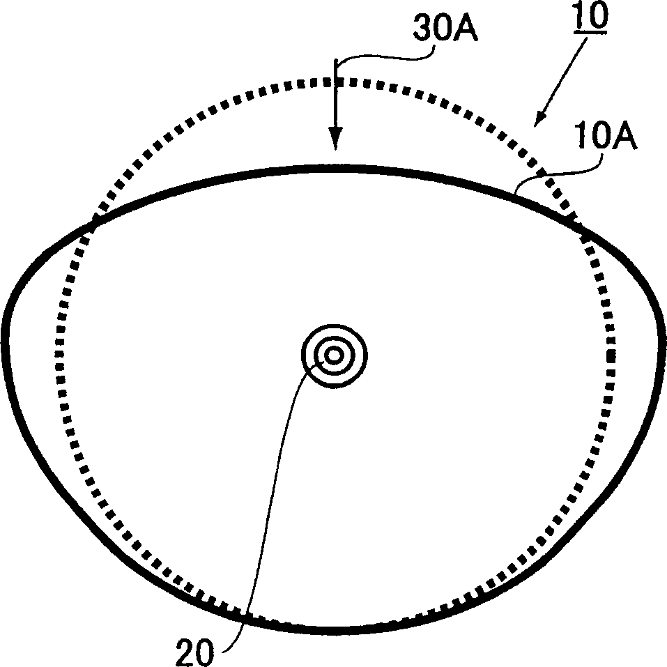
[0035] Preferred embodiments of the present invention will be described below with reference to the drawings. FIG. 1 and FIG. 2 are schematic diagrams of a preferred reflective device for lighting in the present invention. The reflector 10 on the illuminating reflector reflects the light emitted by the light source 20 onto the reflective surface and emits the light in a specific direction from the output opening 10A. image 3The configuration of reflector 10 is shown. Part A in the figure is an enlarged view of the cross section. The reflector 10 is a film-shaped single body, and is formed of a substrate 10a having a concave curved surface and a reflective film 10b formed on the concave curved surface. The reflective film 10b is formed by vapor-depositing metal such as aluminum, and the reflective surface 10B can be formed on the inner surface of the reflector 10 by the reflective film 10b.

[0036] The base material 10a is a bent and formed film-shaped member produced by a ...


PUM

PropertyMeasurementUnit
Thicknessaaaaaaaaaa

Abstract

A lighting reflection apparatus is provided, which improves controllability and sensitivity in changing or controlling an outgoing light characteristic. A reflector is composed of a substrate made of a film-like polyimide molded item shaped using only a difference between pressures applied from respective surfaces of a film-like item while subjecting the film-like item to plasticization with non-contact heating and having in itself a power of maintaining a three-dimensional shape independently or in the form of a single layer, and a reflection surface formed on an inner surface of the substrate. Then, outgoing light is changed or controlled by causing elastic deformation in the reflector by pressing the reflector with pressing means. Since the reflection surface of the reflector is formed by complete non-contact method, it is so smooth that sensitivity in controlling the outgoing light can be improved. Also, since the reflector made of an elastic film is deformed, satisfactory controllability can be attained.

Description

technical field [0001] The present invention relates to a reflection device for illumination, which is equipped with an elastically deformable reflector, and can change or control the outgoing state of irradiated light by elastically deforming the reflector. Background technique [0002] In a lighting reflector equipped with a reflector that can reflect light emitted by a light source in a specific direction, the technology of changing various characteristics of the emitted light or the direction of emission by deforming or moving the reflective surface of the reflector is known technology. For example, in Japanese Patent Publication No. 2-502686 and Japanese Unexamined Publication No. 4-363804, a reflection device for illumination as shown in FIG. The reflective surface of the concave curved surface of the exit opening 1A, the light emitted from the light source 2 is reflected by the reflector 1 and exits from the exit opening 1A; wherein several long grooves 1B are formed...

Claims


Application Information

Patent Timeline
IPC IPC(8): G02B5/10B60Q1/076F21S8/00F21V7/16F21V7/22F21V14/04F21Y101/00
CPCF21V7/22F21W2131/406F21W2131/202F21V7/16B60Q1/076F21W2131/205F21S48/1394F21S48/1757F21S41/37F21S41/67F21S41/675F21V7/24F21V7/28G02B5/10
Inventor 丹野俊广柴田繁男町田英明
Owner DUPONT TORAY CO LTD
Why Eureka
Try Eureka