Method and system for gas-lifting well effluents

Inactive Publication Date: 2003-08-28
SHELL OIL CO
View PDF8 Cites 0 Cited by
  • Summary
  • Abstract
  • Description
  • Claims
  • Application Information

AI Technical Summary

Benefits of technology

0017] It is important to recognise in the present case, that the introduction of mixing elements in a production tubing, wherein productivity is good, will not contribute to a further improvement of the productivity, but rather a reduction due to the increased tall in pressure. Nevertheless, one has in connection with the present invention surprisingly found that the introduction of the mixing elements in a well at falling reservoir pressure, wherein the pressure head in the production tubing gradual

Problems solved by technology

Without such mixing elements the few gas bubbles which appear in the production tubing string, will only be greater and greater

Method used


Image

  • Method and system for gas-lifting well effluents
  • Method and system for gas-lifting well effluents
  • Method and system for gas-lifting well effluents

Examples


Example

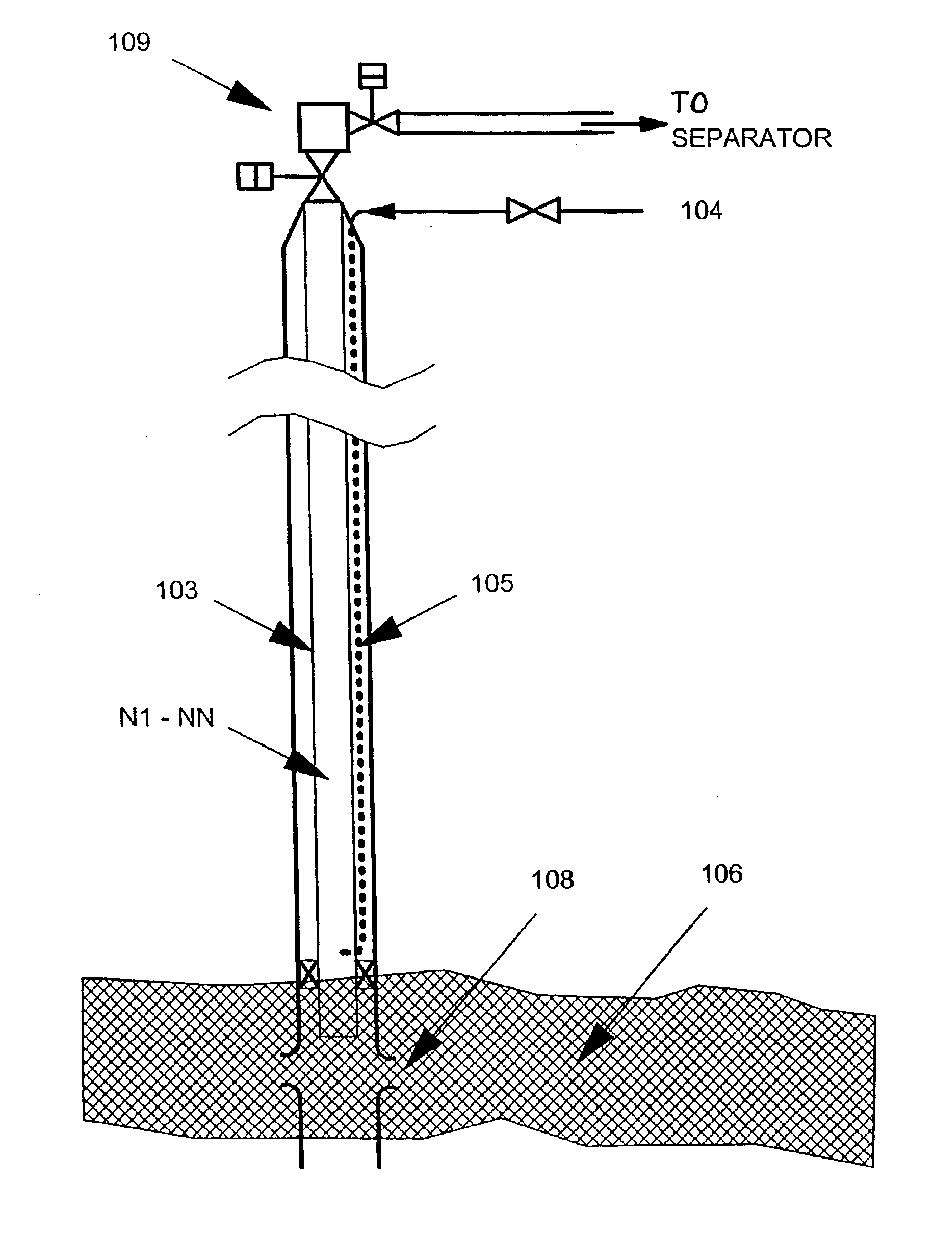
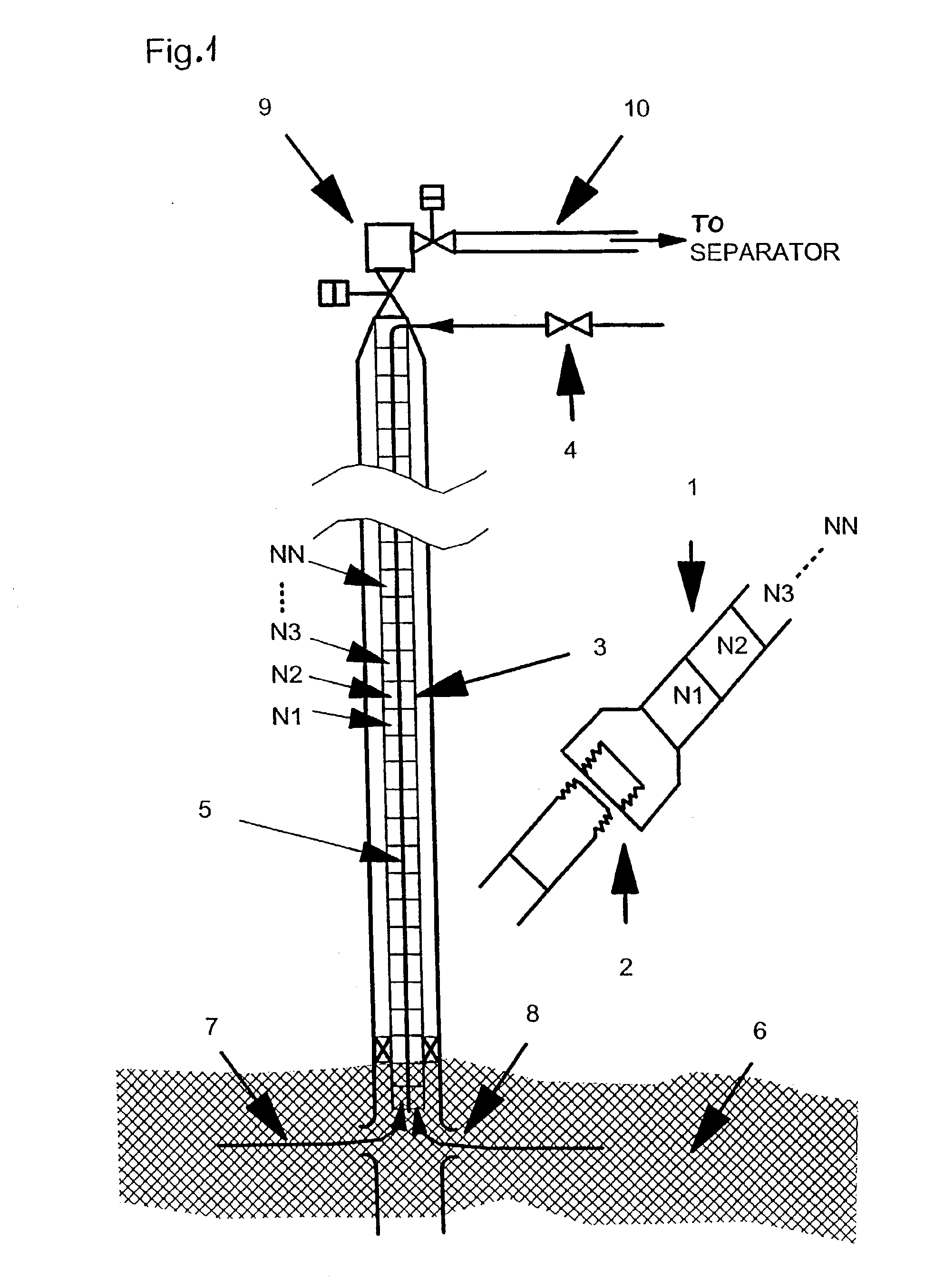
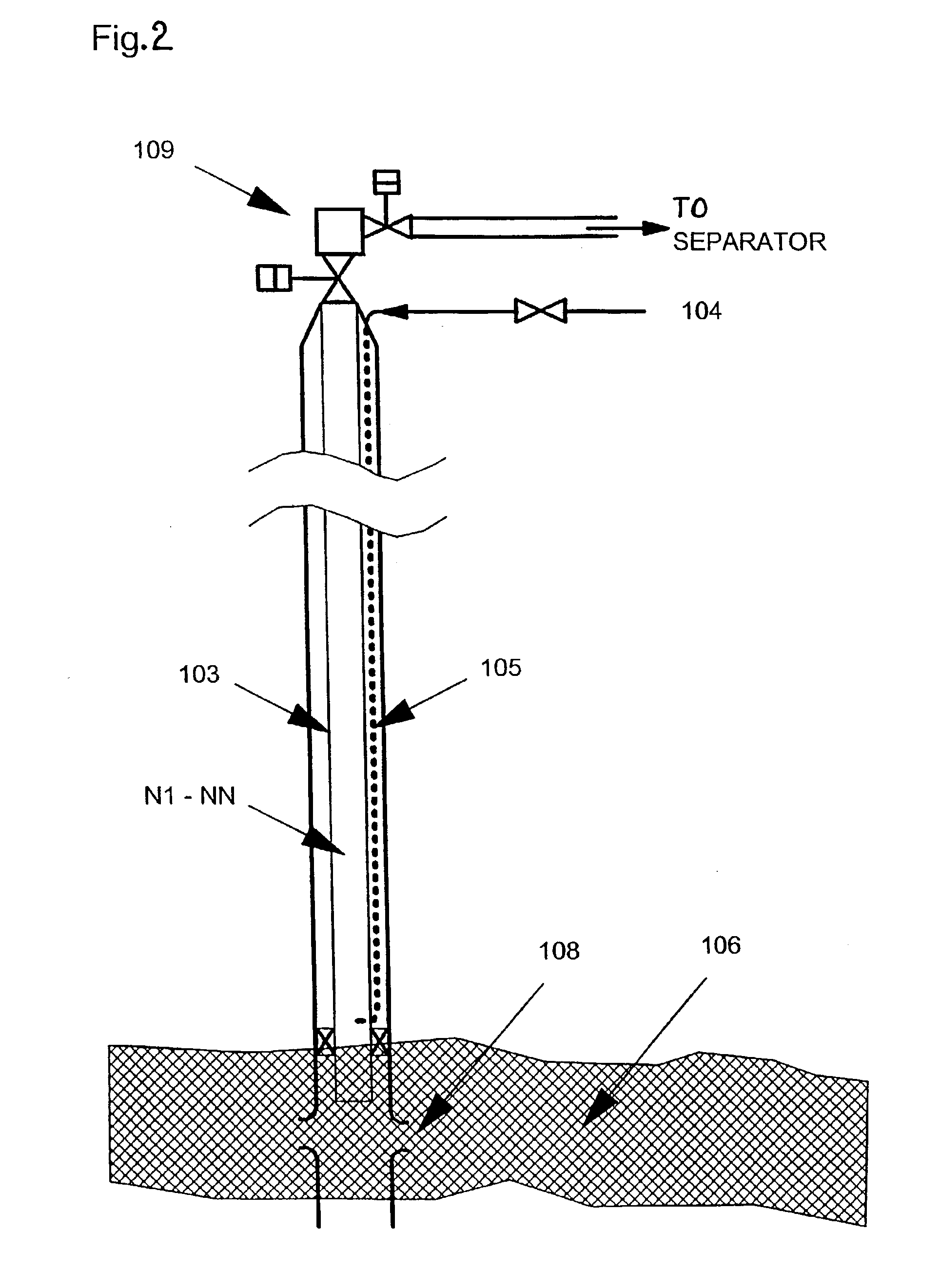
[0023] The invention can be used in a petroleum well with a production tubing string as illustrated in the attached FIG. 1.

[0024] The object of the invention is to stimulate petroleum wells of the type as stated in the attached patent claim 1, and which has terminated--or almost terminated the production, by creating an optimum gas in liquid distribution and an optimum profile of the average gas / liquid density along the extent of the production tubing string.

[0025] This in order to reduce the pressure head resistance at the bottom of the string as regards the flow of gas / liquid out of the reservoir.

[0026] The type of flow patterns which are found in typical production tubings in petroleum wells, is dependent upon gas / oil conditions and the pressure in the reservoir. The invention can be utilised in petroleum wells wherein the liquid portion is decreasing or terminates its flow by low reservoir head. By low head in the reservoir and a great contribution of liquid in the flow from the...


PUM


Abstract

A method and system for gas-lifting well effluents utilizes a porous wall in which an array of small lift-gas injection ports is present such that lift-gas is injected as an agglomerate of finely dispersed micro-bubbles into the stream of well effluents. In this way the lift-gas and produced crude oil form a froth and the risk of slugs of lift-gas that bypass slugs of crude oil and create an unstable flow regime is minimized.

Description

[0001] The following invention relates to a use in connection with transport or flow through a production tubing string in a petroleum well of gas and liquid from a petroleum reservoir with low pressure, where the flowing fluid comprises a substantial liquid part and a less gas contribution, which gas mostly flows or bubbles past or through the liquid in the production tubing.[0002] in other words, it can be said that the present invention relates mainly to the type of petroleum wells which may be termed an oil producer, such oil producer producing mainly oil and some gas. This is different from petroleum wells (reservoirs) which are termed gas producer's, which gas producers often also produce some liquid, for example in the form of condensate and water. By such a liquid production (in a gas well) and low pressure in the reservoir, such a well could, however, gradually "drown", and the need for gas lift may be required. Thus, the present invention also relates to gas lift for gas w...

Claims


Application Information

Patent Timeline
IPC IPC(8): E21B43/12E21B43/00
CPCE21B43/123E21B43/122
Inventor ELLEPOLA, JEROME HANSABHAYAOLIEMANS, RENE VICTOIRE ADOLF
Owner SHELL OIL CO
Why Eureka
Try Eureka