Ductless ventilation method for underground water treatment structure

A ventilation method and water treatment technology, which is applied to drainage structures, buildings, waterway systems, etc., can solve the problems of many crossing conflicts of deodorizing pipes, difficulties in construction and hoisting, and large amount of installation and maintenance works, so as to reduce the operating capacity of the system The effect of reducing power consumption and fan operation noise, improving ventilation efficiency and sewage discharge efficiency, and reducing initial investment in civil engineering

Pending Publication Date: 2019-03-08
SHANGHAI MUNICIPAL ENG DESIGN INST GRP
View PDF0 Cites 2 Cited by
  • Summary
  • Abstract
  • Description
  • Claims
  • Application Information

AI Technical Summary

Problems solved by technology

Large-section air ducts occupy most of the pipeline space, often intersect with cable trays, fire water pipes, reclaimed water or water supply pipes, and deodorizing pipes.
In order to avoid the above conflicts and ensure the necessary pipe spacing for different types of pipes, large-section air ducts often increase the buried depth of the entire underground box by 1~2m, resulting in a substantial increase in civil engineering investment
On the other hand, a large number of air ducts will also cause a large amount of installation and maintenance work, and difficulties in construction and hoisting.
From the perspective of ventilation effect, this traditional ventilation method with air supply and exhaust pipes generally has many problems such as ventilation dead zone, poor ventilation uniformity, high energy consumption, and high noise.

Method used


Image

  • Ductless ventilation method for underground water treatment structure
  • Ductless ventilation method for underground water treatment structure
  • Ductless ventilation method for underground water treatment structure

Examples


Embodiment

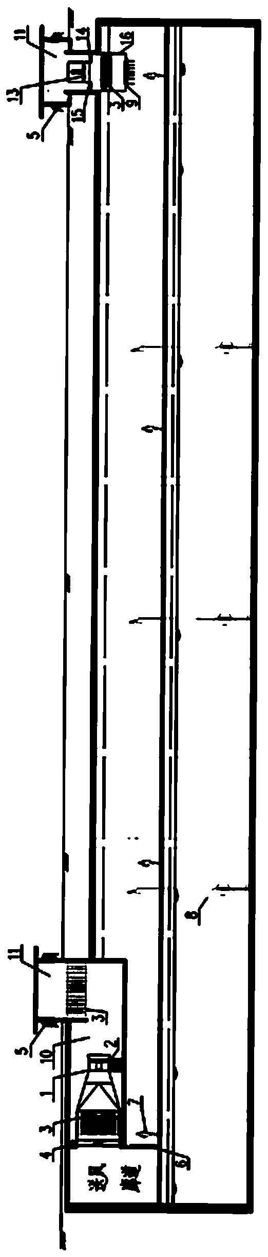
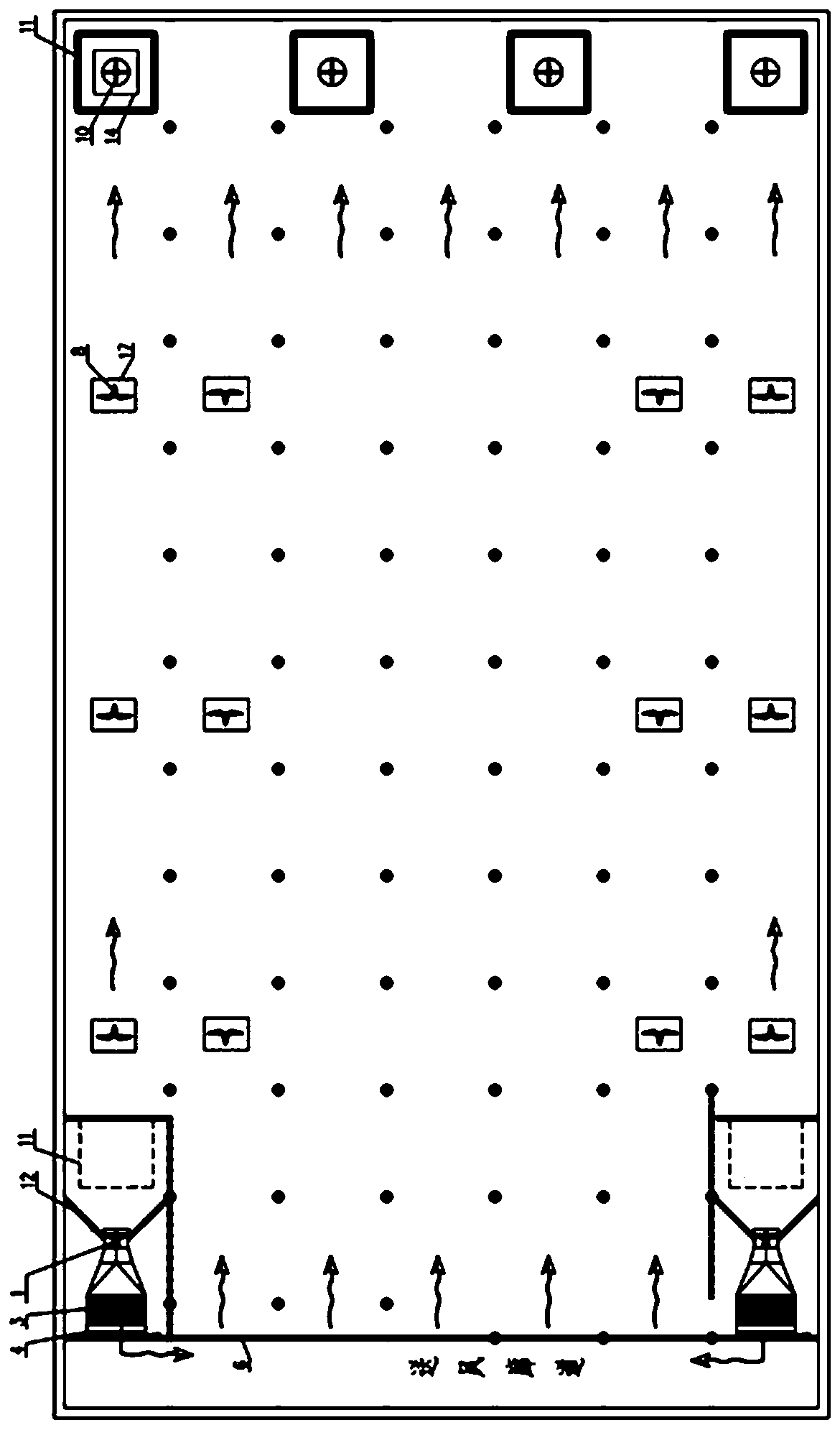
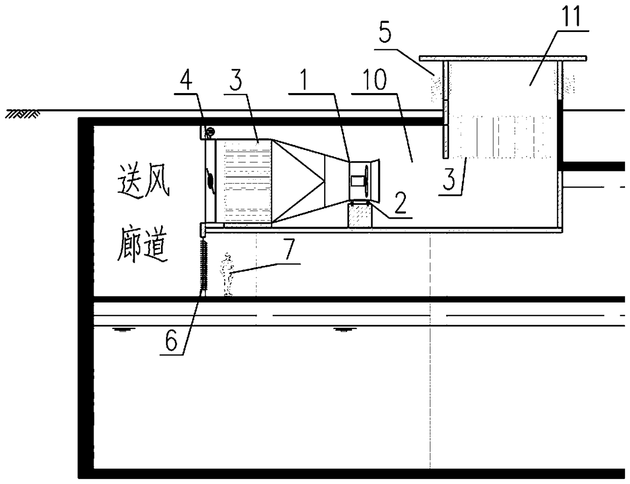
[0026] Embodiment: This embodiment specifically relates to a ductless ventilation system for underground water treatment structures, which has high ventilation efficiency and sewage discharge efficiency, low air age, less ventilation stagnation areas, and good uniformity of air supply and exhaust. With the advantages of low energy consumption and low noise, it can effectively reduce the overall buried depth of underground water treatment structures, reduce the pressure head of fans, and save initial investment in project construction and operation and maintenance costs such as image 3 As shown, the ductless ventilation system of an underground water treatment structure consists of an air intake unit, an air supply corridor, a ventilation target area, and an exhaust unit.

[0027] The air intake unit includes: air blower 1, spring shock absorber 2, array muffler 3, electric control valve 4, muffler and rainproof louvers 5, air intake channel 10, air well 11, deflector 12.

[0...


PUM


Abstract

The invention discloses a ductless ventilation method for an underground water treatment structure. The method includes the following steps that after an air supply fan is turned on, outdoor fresh airenters an air supply well; the fresh air enters the air supply well after passing through an array muffler located in the air supply well; after being pressurized with a pressure fan, fresh air reaches the array muffler at an air outlet of the pressure fan and then is introduced to an air supply corridor through an electric regulating valve, an outlet louver of the air supply corridor is adjusted, and fresh air is sent to a target ventilation area in the form of one-way piston flow through the air supply corridor, and air carrying indoor gaseous pollutants is discharged by an exhaust fan. A ductless ventilation system is arranged in the target ventilation area, thus the system is attractive, the burial depth of an underground sewage treatment plant is reduced, and the initial investment in civil engineering is reduced, the air age and the pollutant concentration in the patrol area of large space are reduced, and the ventilation efficiency and the sewage discharge efficiency are improved.

Description

technical field [0001] The invention relates to the field of water treatment, in particular to a ductless ventilation method suitable for underground water treatment structures. Background technique [0002] The underground water treatment structure transfers the water treatment facilities from the open air to the underground. It has the advantages of strong sealing, environmental friendliness, small footprint, can improve the quality of surrounding plots, organically integrates with greening and water features, and has good aesthetics. Recognized by local governments and surrounding residents, the demand for construction has increased sharply, and it has become a new direction for urban water treatment engineering construction. [0003] Underground water treatment structures are generally divided into three layers: the ground layer usually includes a number of ventilation shafts, entrances and exits, etc., and most of the rest are soil-covered greening; the basement layer i...

Claims


Application Information

Patent Timeline
Patent Type & Authority Applications(China)
IPC IPC(8): E03F5/08
CPCE03F5/08
Inventor 张欣董磊肖艳郑凯高乃平朱学海
Owner SHANGHAI MUNICIPAL ENG DESIGN INST GRP
Why Eureka
Try Eureka