
Pipe group isolation pipe-jacking construction method

A construction method and pipe jacking technology, which is applied in earthwork drilling, wellbore lining, tunnel lining, etc., can solve problems such as increasing project risk and cost, lengthening open-cut and buried sections, and increasing the thickness of segments to achieve social effects Significantly, reduce the effect of covering soil and reducing settlement deformation

Inactive Publication Date: 2020-05-29
SHANGHAI URBAN CONSTR DESIGN RES INST GRP CO LTD
View PDF6 Cites 1 Cited by
  • Summary
  • Abstract
  • Description
  • Claims
  • Application Information

AI Technical Summary

Problems solved by technology

[0003] (1) The thickness of the segment increases due to the increase of the covering soil;
[0004] (2) As a result, the open-cut and buried sections of pipe jacking wells and tunnels are lengthened, and the excavation depth is increased, which directly increases the project risk and cost;
[0005] (3) lead to take up more valuable urban underground space
[0008] (1) High cost;
[0009] (2) As the supporting structure of the construction stage, the pipe curtain must be designed to be relatively strong, but it will lose its function after the construction of the permanent structure is completed, which is wasteful
[0010] (3) Jacking is also required for pipe curtain construction, and its size is relatively large, generally about 800-1000mm in diameter, which also affects the ground surface
[0011] (4) Flower pipe grouting must be used in the construction of pipe curtains to form a strong vertical support structure, but the grouting itself is easy to cause deformation of the ground surface

Method used


Image

  • Pipe group isolation pipe-jacking construction method
  • Pipe group isolation pipe-jacking construction method
  • Pipe group isolation pipe-jacking construction method

Examples


Embodiment

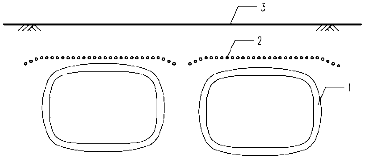
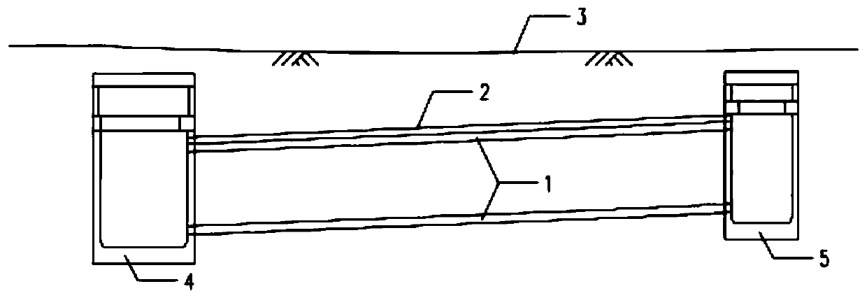
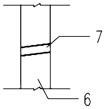
[0035] Such as Figure 1 to Figure 4 As shown in the pipe group isolation pipe jacking construction method, there are deformation-sensitive structures on the ground 3; the steps are as follows:

[0036] Step 1, pre-embed a number of seamless steel pipe guide pipes 7 in the side wall 6 of the originating shaft 4 of the pipe jacking 1;

[0037] Step 2: Drilling a number of seamless steel pipes 2 above the corresponding pipe jacking 1 by micro-pipe jacking technology to form a group of ribbed pipes; each seamless steel pipe 2 extends from the starting shaft 4 along the corresponding seamless steel pipe guide pipe out, and penetrate into the receiving well 5 of the pipe jacking 1;

[0038] The laying elevation angle of each seamless steel pipe 2 must be kept within the range of 1:1 to 1:1.2 with the corresponding pipe jacking 1 elevation angle, and the laying length range should be more than 4m beyond the outer edge of the structure on the ground;

[0039] Step 3: After the seam...


PUM


Abstract

The invention discloses a pipe group isolation pipe-jacking construction method, which is suitable for structures sensitive to deformation on the ground. The method comprises the following steps thatfirstly, a plurality of seamless steel tube guide pipes are pre-buried in a side wall of a pipe-jacking originating well; secondly, a plurality of seamless steel pipes are arranged above a corresponding jacking pipe through a miniature pipe jacking technology, and therefore a rib pipe group is formed; each seamless steel pipe extends out of an originating well along the corresponding seamless steel pipe guide pipe and penetrates into a receiving well of the jacking pipe; thirdly, after the seamless steel pipes are arranged, slurry is injected into each seamless steel pipe; after the slurry issolidified, the construction of the rib pipe group is completed; and finally, construction of the jacking pipe is conducted. The construction method gives consideration to economical efficiency and practicability, and disturbance to an upper soil body can be effectively isolated during pipe jacking construction under the condition that the upper soil body of a pipe jacking section is not excavatedor damaged, influence of construction on the surrounding environment is reduced, the tunnel burial depth is decreased, the underground space is saved, and therefore remarkable social benefits are achieved.

Description

technical field [0001] The invention relates to the technical field of underground pipe jacking engineering, in particular to a pipe group isolated pipe jacking construction method. Background technique [0002] The pipe jacking method is a construction method that has little impact on ground structures, and the impact on the ground surface is often controlled by controlling the thickness of the soil above the pipe jacking. However, as the size of the pipe jacking section becomes larger and larger, controlling the deformation by thickening the cover soil thickness will bring the following unfavorable factors: [0003] (1) The thickness of the segment increases due to the increase of the covering soil; [0004] (2) As a result, the open-cut and buried sections of pipe jacking wells and tunnels are lengthened, and the excavation depth is increased, which directly increases the project risk and cost; [0005] (3) lead to taking more valuable urban underground space. [0006]...

Claims


Application Information

Patent Timeline
Patent Type & Authority Applications(China)
IPC IPC(8): E21D9/00E21D11/14E21D11/10
CPCE21D9/00E21D11/10E21D11/14
Inventor 王印昌吴正恺姜弘王晓波
Owner SHANGHAI URBAN CONSTR DESIGN RES INST GRP CO LTD
Learn More