
Flexible pipe joint having an annular flexible boot thermally or chemically insulating an annular elastomeric flexible element

a flexible pipe joint and annular flexible technology, applied in the direction of adjustable joints, drilling pipes, mechanical equipment, etc., can solve the problems of reducing performance and elastomeric flexible elements, and achieve the effects of less space, reliable installation, and convenient installation

Active Publication Date: 2019-07-02
WELLS FARGO BANK NAT ASSOC +1
View PDF56 Cites 2 Cited by
  • Summary
  • Abstract
  • Description
  • Claims
  • Application Information

AI Technical Summary

Benefits of technology

The annular flexible boot offers improved thermal and chemical insulation, reduced weight, and increased reliability with a more compact design, potentially replacing or complementing two-stage bellows, while being less sensitive to buckling and pressure loads.

Problems solved by technology

A limitation of the elastomeric flexible elements is reduced performance when exposed to heat from fluid flowing in the pipeline or riser, and to chemicals in the fluid.

Method used


Image

  • Flexible pipe joint having an annular flexible boot thermally or chemically insulating an annular elastomeric flexible element
  • Flexible pipe joint having an annular flexible boot thermally or chemically insulating an annular elastomeric flexible element
  • Flexible pipe joint having an annular flexible boot thermally or chemically insulating an annular elastomeric flexible element

Examples


Embodiment Construction

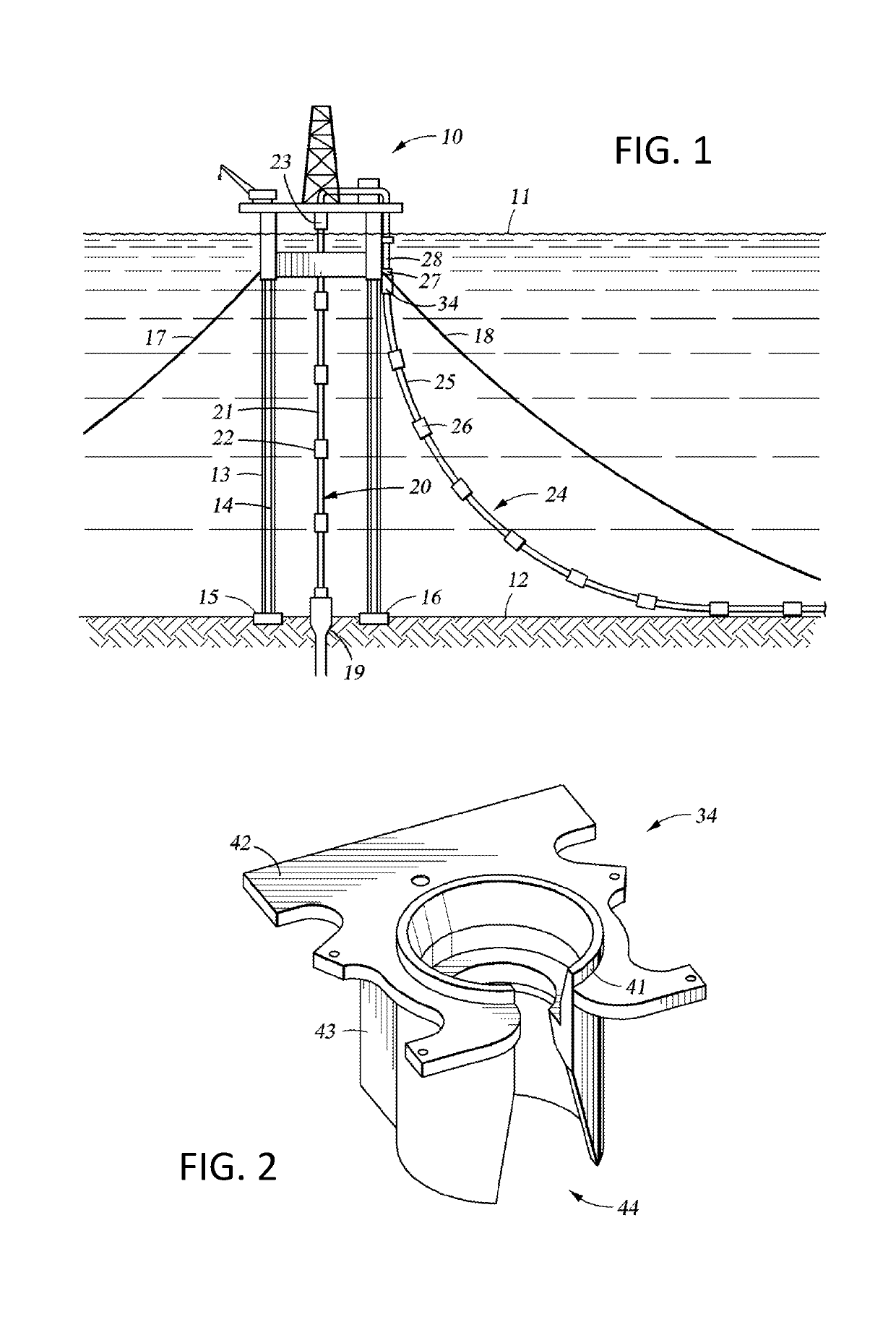
[0042]With reference to FIG. 1, there is shown an offshore drilling and production vessel generally designated 10 floating on a water surface 11. The floating vessel in particular is a tension leg platform (TLP) secured to the seabed 12 by means of tendons 13, 14 and foundation templates 15, 16. Although not visible in FIG. 1, there is a set of tendons depending from each of four corners of the TLP platform 10 to a respective one of four foundation templates 15, 16. In addition, each of the four lower corners of the TLP platform 10 is secured by a respective lateral mooring line 17, 18 used to move the platform laterally and to resist lateral storm loadings.

[0043]For conveying drilling fluids and a drill string from the TLP to a well bore 19 in the seabed 12, and for removing hydrocarbons from the well when drilling has been completed, a production riser generally designated 20 extends from the well bore 19 up to the TLP 10. The riser 20 consists of a number of rigid pipe sections 2...


PUM


Abstract

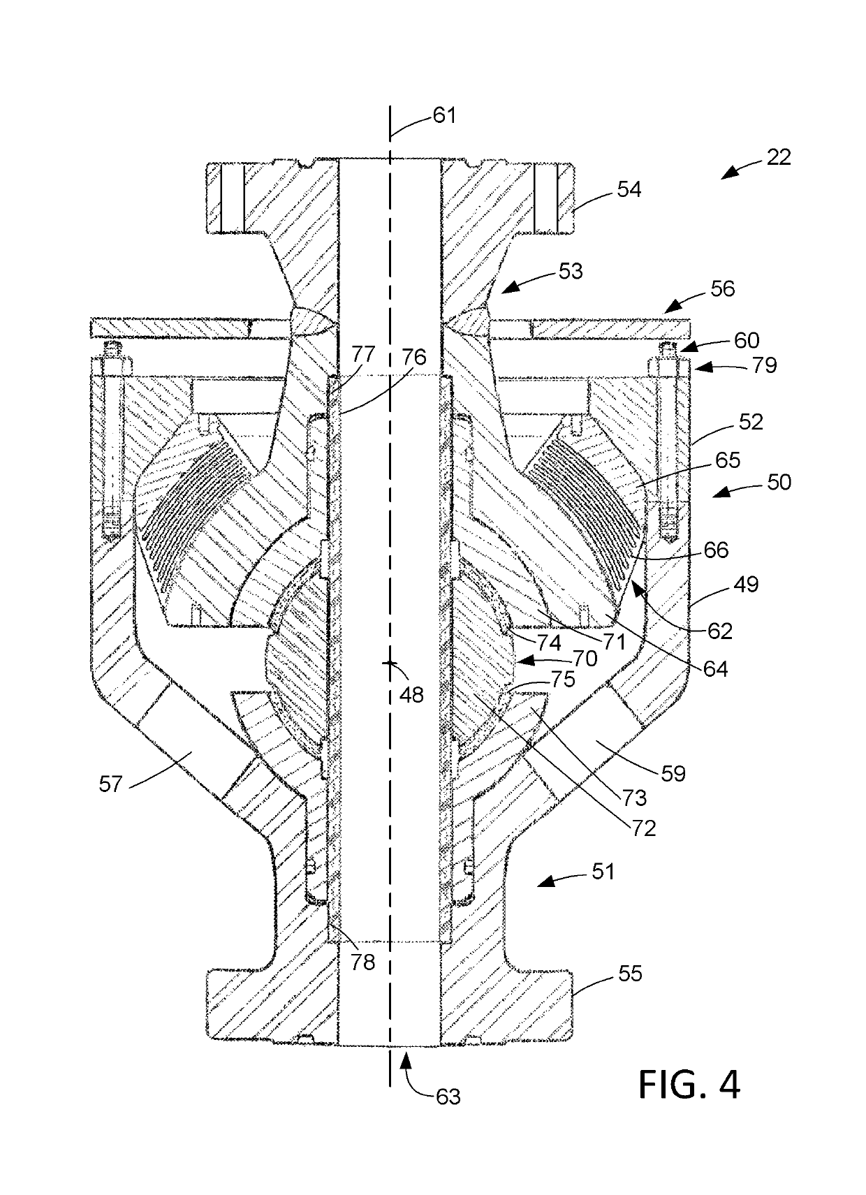
A flexible pipe joint has a body and an annular elastomeric flexible element flexibly coupling an extension pipe to the body for pivoting of the extension pipe with respect to the body. The flexible pipe joint also has an annular flexible boot for thermally or chemically insulating the annular elastomeric flexible element from the fluid flowing through a lumen of the flexible pipe joint. The annular flexible boot encircles the lumen, and the annular flexible boot has a first annular end attached to the extension pipe and a second annular end mounted so that pivoting of the extension pipe with respect to the body causes a flexing of the annular flexible boot, and a majority of the annular flexible boot has a shape conforming to shape of neighboring components of the flexible pipe joint.

Description

RELATED APPLICATION[0001]The present application claims the benefit of James G. Patrick et al. U.S. Provisional Application 62 / 168,707 filed May 29, 2015 entitled “Thermal or Chemical Insulating Boot for Flexible Elements,” incorporated herein by reference.FIELD OF THE INVENTION[0002]The present invention relates to an annular flexible boot for insulating an annular elastomeric flexible element in a flexible pipe joint from thermal or chemical exposure to fluid flowing through the flexible pipe joint.BACKGROUND ART[0003]Elastomeric flexible elements are often used in the oil industry in flexible pipe joints for coupling or supporting segments of a pipeline or riser. A limitation of the elastomeric flexible elements is reduced performance when exposed to heat from fluid flowing in the pipeline or riser, and to chemicals in the fluid. A conventional way of dealing with this limitation is by using a two-stage bellows.[0004]For example, as described in Whightsil, Sr. et al. U.S. Pat. No...

Claims


Application Information

Patent Timeline
Patent Type & Authority Patents(United States)
IPC IPC(8): F16L27/103F16L59/18E21B17/08
CPCF16L27/103F16L59/185E21B17/085E21B17/08
Inventor PATRICK, JAMES G.LUKE, ERICGUTIERREZ-LEMINI, DANTON
Owner WELLS FARGO BANK NAT ASSOC
Learn More