RF antenna assembly with series dipole antennas and coupling structure and related methods

a dipole antenna and antenna assembly technology, applied in the direction of fluid removal, insulation, borehole/well accessories, etc., can solve the problems of high viscosity hydrocarbon resources, such as heavy oils, being consumed, and increasing energy consumption worldwid

Active Publication Date: 2015-11-10
HARRIS CORP
View PDF49 Cites 2 Cited by
  • Summary
  • Abstract
  • Description
  • Claims
  • Application Information

AI Technical Summary

Benefits of technology

[0012]In view of the foregoing background, it is therefore an object of the present invention to provide an RF antenna assembly that is physically robust and flexible.
[0013]This and other objects, features, and advantages in accordance with the present invention are provided by an RF antenna assembly configured to be positioned within a wellbore in a subterranean formation for hydrocarbon resource recovery. The RF antenna assembly includes a series of tubular dipole antennas to be positioned within the wellbore, each tubular dipole antenna comprising a pair of dipole elements, an RF transmission line extending within the series of tubular dipole antennas, and a respective coupling structure between each pair of dipole elements and between the series of tubular dipole antennas. Each coupling structure comprises a dielectric tube mechanically coupling adjacent dipole elements, and at least one tap connector carried by the dielectric tube and electrically coupling the RF transmission line to a corresponding dipole element. Advantageously, the RF antenna assembly may efficiently heat the hydrocarbons.

Problems solved by technology

Energy consumption worldwide is generally increasing, and conventional hydrocarbon resources are being consumed.
For example, highly viscous hydrocarbon resources, such as heavy oils, may be trapped in sands where their viscous nature does not permit conventional oil well production.
The SAGD process may be relatively sensitive to shale streaks and other vertical barriers since, as the rock is heated, differential thermal expansion causes fractures in it, allowing steam and fluids to flow through.
Oil is not yet produced from oil sands on a significant level in other countries.
Unfortunately, long production times, for example, due to a failed start-up, to extract oil using SAGD may lead to significant heat loss to the adjacent soil, excessive consumption of steam, and a high cost for recovery.
Limited water resources may also limit oil recovery.
SAGD is also not an available process in permafrost regions, for example, or in areas that may lack sufficient cap rock, are considered “thin” payzones, or payzones that have interstitial layers of shale.
For example, it may be relatively difficult to install or integrate RF heating equipment into existing wells.

Method used


Image

  • RF antenna assembly with series dipole antennas and coupling structure and related methods
  • RF antenna assembly with series dipole antennas and coupling structure and related methods
  • RF antenna assembly with series dipole antennas and coupling structure and related methods

Examples


Embodiment Construction

[0035]The present invention will now be described more fully hereinafter with reference to the accompanying drawings, in which preferred embodiments of the invention are shown. This invention may, however, be embodied in many different forms and should not be construed as limited to the embodiments set forth herein. Rather, these embodiments are provided so that this disclosure will be thorough and complete, and will fully convey the scope of the invention to those skilled in the art. Like numbers refer to like elements throughout, and prime notation is used to indicate similar elements in alternative embodiments.

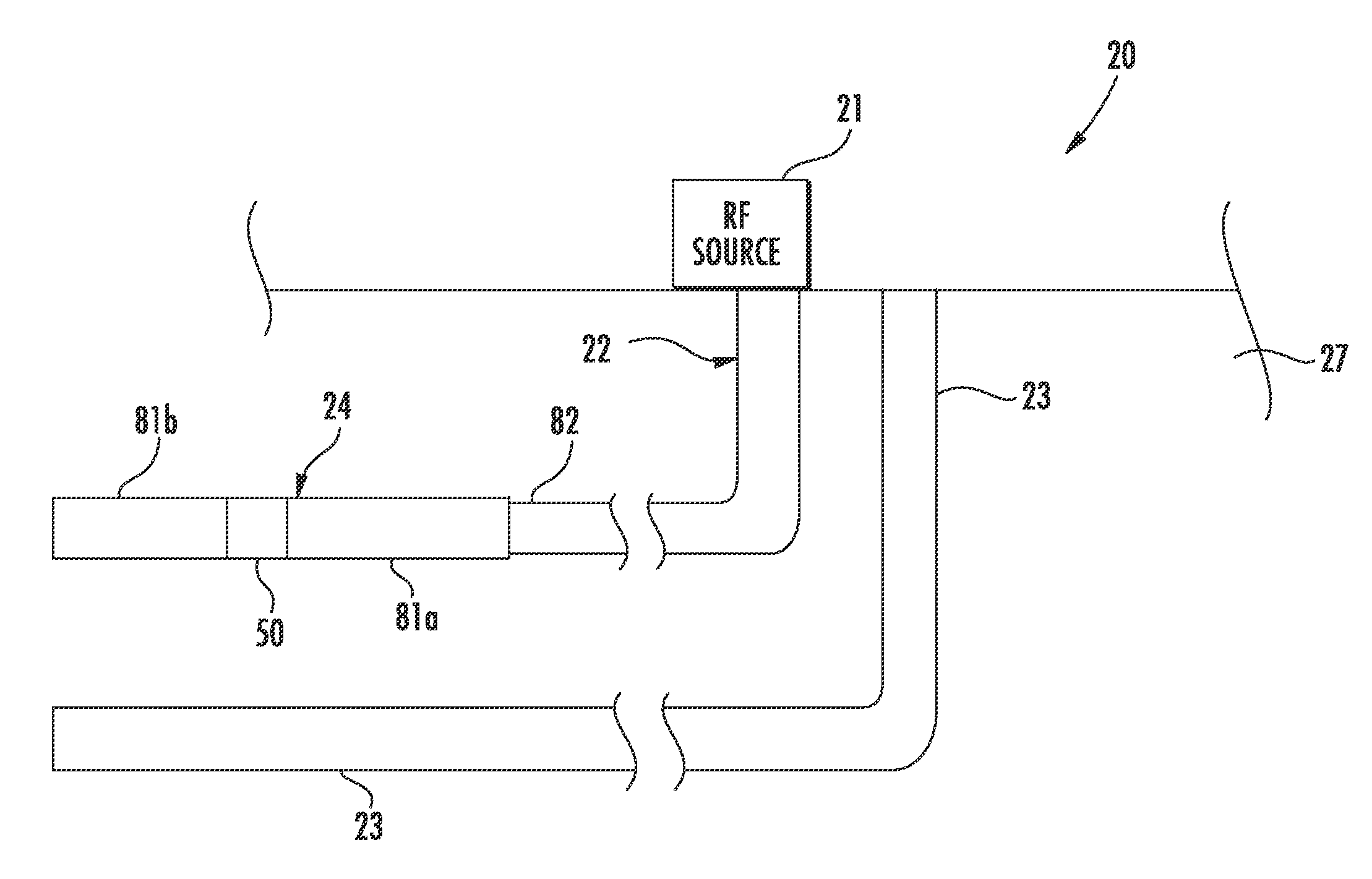
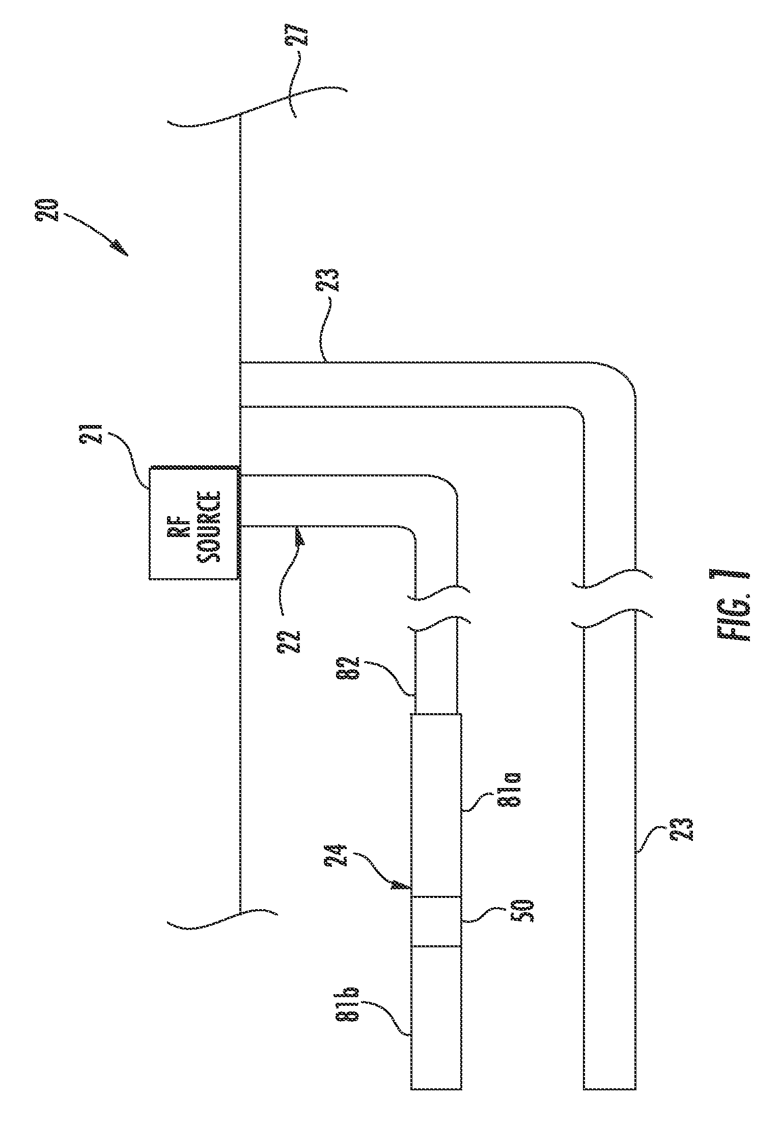
[0036]Referring initially to FIGS. 1-2, a hydrocarbon recovery system 20 according to the present invention is now described. The hydrocarbon recovery system 20 includes an injector well 22, and a producer well 23 positioned within respective wellbores in a subterranean formation 27 for hydrocarbon recovery. The injector well 22 includes an antenna assembly 24 at a distal e...


PUM


Abstract

An RF antenna assembly is to be positioned within a wellbore in a subterranean formation for hydrocarbon resource recovery. The RF antenna assembly includes a series of tubular dipole antennas to be positioned within the wellbore, each tubular dipole antenna having a pair of dipole elements, and an RF transmission line extending within the series of tubular dipole antennas. The RF antenna assembly includes a respective coupling structure between each pair of dipole elements and between the series of tubular dipole antennas, each coupling structure including a dielectric tube mechanically coupling adjacent dipole elements, and a tap connector carried by the dielectric tube and electrically coupling the RF transmission line to a corresponding dipole element.

Description

FIELD OF THE INVENTION[0001]The present invention relates to the field of hydrocarbon resource processing, and, more particularly, to an antenna assembly isolator and related methods.BACKGROUND OF THE INVENTION[0002]Energy consumption worldwide is generally increasing, and conventional hydrocarbon resources are being consumed. In an attempt to meet demand, the exploitation of unconventional resources may be desired. For example, highly viscous hydrocarbon resources, such as heavy oils, may be trapped in sands where their viscous nature does not permit conventional oil well production. This category of hydrocarbon resource is generally referred to as oil sands. Estimates are that trillions of barrels of oil reserves may be found in such oil sand formations.[0003]In some instances, these oil sand deposits are currently extracted via open-pit mining. Another approach for in situ extraction for deeper deposits is known as Steam-Assisted Gravity Drainage (SAGD). The heavy oil is immobile...

Claims


Application Information

Patent Timeline
Patent Type & Authority Patents(United States)
IPC IPC(8): E21B43/24E21B36/04
CPCE21B43/2401E21B36/04
Inventor WRIGHT, BRIANHANN, MURRAYHEWIT, RAYMONDJACKSON, JR., RONALD EDWARD
Owner HARRIS CORP
Why Eureka
Try Eureka