Terminal and terminal-provided wire

a technology of providing wires and terminals, applied in the direction of connection contact materials, connections effected by permanent deformation, coupling device connections, etc., can solve the problems of more serious core breakage (strand breakage), and the problem of core breakage (strand breakage) is serious, and achieves easy breakage and good electrical connection performance.

Active Publication Date: 2015-11-10
AUTONETWORKS TECH LTD +2
View PDF11 Cites 7 Cited by
  • Summary
  • Abstract
  • Description
  • Claims
  • Application Information

AI Technical Summary

Benefits of technology

[0019]According to the present invention, it is possible to provide a terminal-provided wire which has good electrical connection performance between a terminal and a wire (core) and is easily breakable at the time of disassembling and a terminal utilized therefor.

Problems solved by technology

Thus, there is a possibility of core breakage (strand breakage) in that part.
Thus, the problem of core breakage (strand break) is more serious.

Method used


Image

  • Terminal and terminal-provided wire
  • Terminal and terminal-provided wire
  • Terminal and terminal-provided wire

Examples


first embodiment

Version (2)

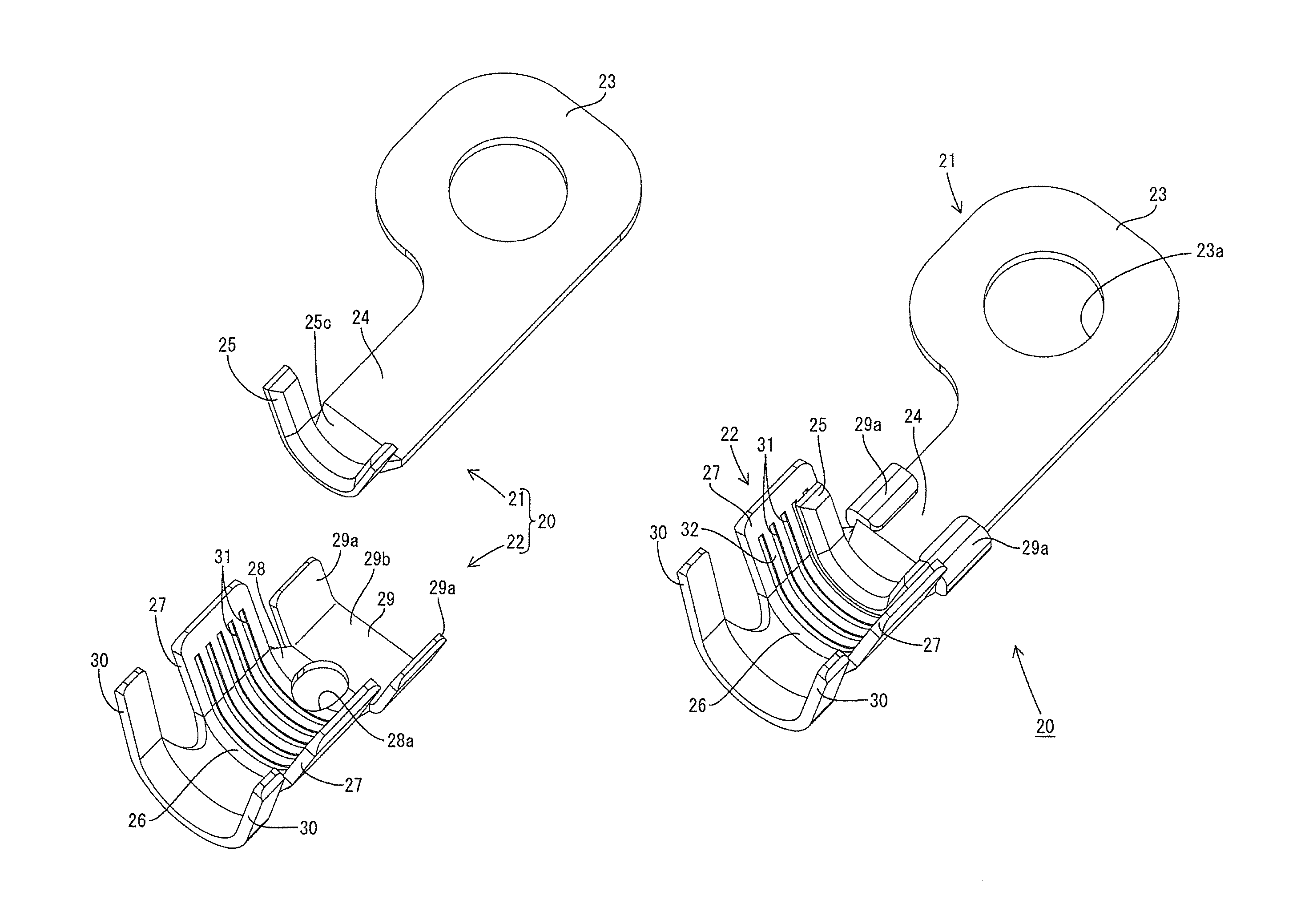
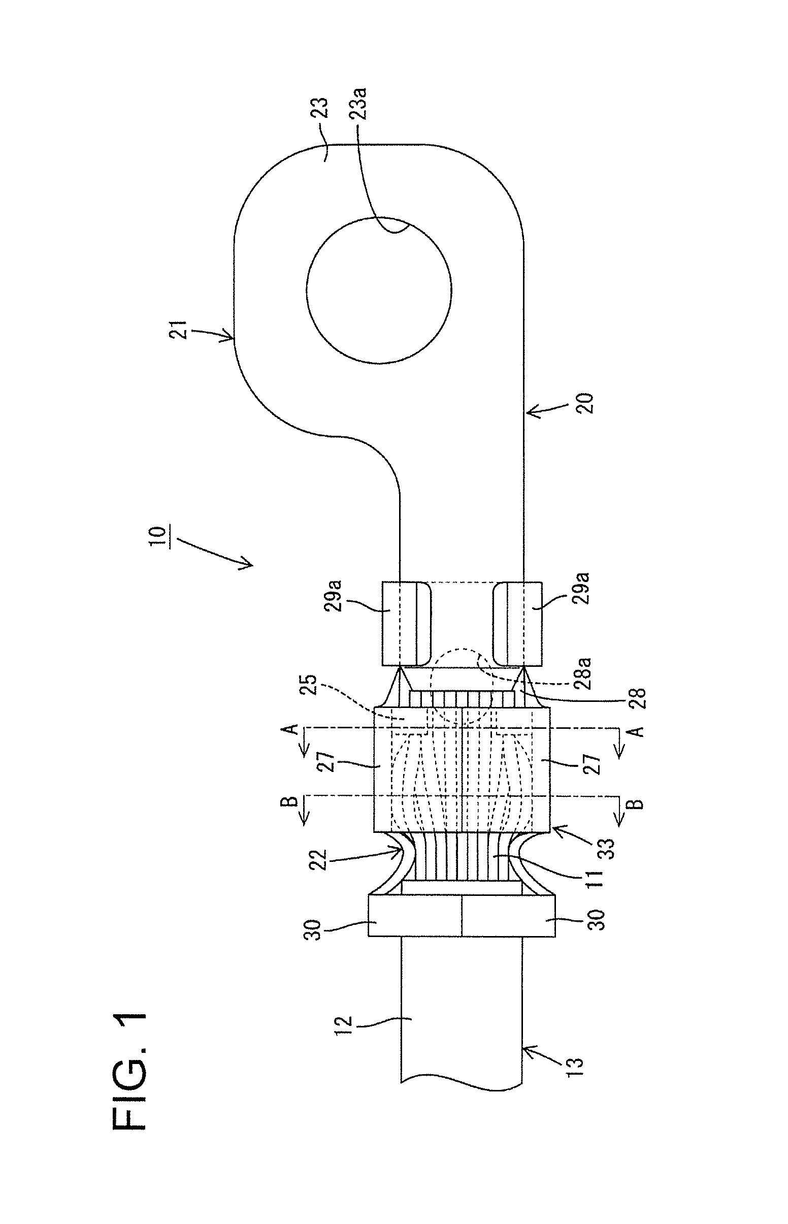
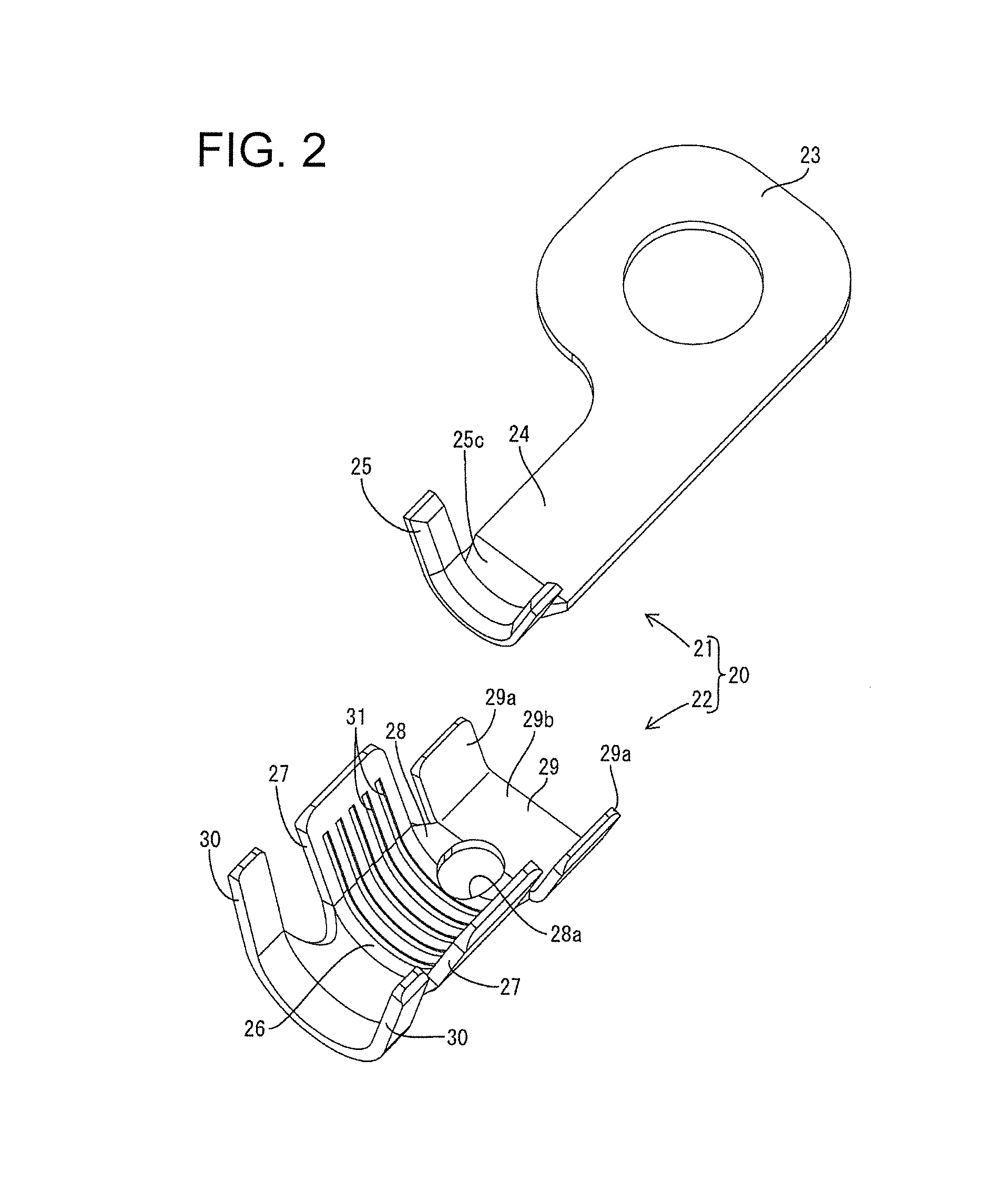
[0083]Next, a second version of the first embodiment is described with reference to FIGS. 10 and 11. Note that the same components as in the first version of the first embodiment illustrated in FIGS. 1 to 9 are denoted by the same reference signs and not described in detail. FIG. 10 is an exploded perspective view of a terminal 20A in the second version of the first embodiment and FIG. 11 is a perspective view of the terminal 20A in the second version of the first embodiment (2). The terminal 20A of this embodiment is a ground terminal as in the first embodiment (1) and used by being crimped to an end part of a wire 13 similar to that of the first embodiment (1).

[0084]As shown in FIG. 10, the terminal 20A of this embodiment is composed of a front terminal portion 21A and a rear terminal portion 22A. The configuration of the front terminal portion 21A of this embodiment is the same as the front terminal portion 21 of the first embodiment (1). Further, the configuration of ...

second embodiment

[0085]Conventionally, a terminal-provided wire including a wire with a core and a terminal connected to the core exposed at an end of the wire is known from Japanese Unexamined Patent Publication No. 2010-62097.

[0086]An oxide film may be formed on a core surface of a part where a terminal is to be crimped. This oxide film is a cause of increasing electric resistance between the core and the terminal and electric resistance among strands constituting the core. Thus, as described in patent literature 1, a barrel is wound around the core with a high pressure, thereby crushing and destroying the oxide film, when the terminal is mounted on the core. If the oxide film is destroyed, a new core surface (new surface), which is not oxidized, appears from below. This new surface is utilized such as for electrical connection between the core and the terminal, thereby reducing the electric resistance described above.

[0087]A ground terminal to be connected to an end of a core of a ground wire is ...


PUM


Abstract

A terminal-provided wire (10) includes a wire (13) with a core (11) whose end is exposed, and a terminal (20) crimped to the end of the core (11) and connectable to a mating side. The terminal (20) includes a front terminal portion (21) and a rear terminal portion (22). The rear terminal portion (22) includes a bottom plate portion (26) on which the core (11) is to be placed, a pair of wire barrel portions (27) extending from the bottom plate portion (26) and to be crimped to the core (11), an easily breakable portion (28) extending in an axial direction from the bottom plate portion (26) and to be broken at the time of disassembling, and a fixing portion (29) extending in the axial direction from the easily breakable portion (28). The front terminal portion (21) includes an auxiliary crimping portion (25) to be placed on the bottom plate portion (26) in such a manner as to be sandwiched between the bottom plate portion (26) and the core (22) and to be crimped to the core (22) together with the wire barrel portions (27) to partly highly compress the core (22), a fixing portion (24) to be fixed to the fixing portion (29) and a connecting portion (23) extending in the axial direction from the fixing portion (24).

Description

BACKGROUND[0001]1. Field of the Invention[0002]The present invention relates to a terminal and a terminal-provided wire.[0003]2. Description of the Related Art[0004]Conventionally, there is known a terminal-provided wire in which a terminal is mounted on an end of an exposed core of a wire. This terminal includes a barrel in the form of a plate piece, and the terminal and the core are electrically connected by crimping (caulking) this barrel in such a manner as to be wind around the core.[0005]An oxide film may be formed on a part of a core surface on which the terminal is to be crimped. This oxide film is a cause of increasing electric resistance between the core and the terminal and electric resistance among strands constituting the core. Thus, as described in Japanese Unexamined Patent Publication No. 2010-62097, the barrel is wound around the core with a high pressure in mounting the terminal on the core, thereby crushing and destroying the oxide film. If the oxide film is destr...

Claims


Application Information

Patent Timeline
Patent Type & Authority Patents(United States)
IPC IPC(8): H01R4/10H01R13/633H01R4/20H01R4/62H01R4/18
CPCH01R13/633H01R4/20H01R4/206H01R4/62H01R4/185
Inventor MIYAMOTO, KENJIONO, JUNICHIOOTA, TOSHIYAOTSUKA, TAKUJITONOSAKI, TAKASHI
Owner AUTONETWORKS TECH LTD
Why Eureka
Try Eureka