Master input device and master-slave manipulator

a master-slave and input device technology, applied in the direction of electric programme control, program control, instruments, etc., can solve the problem of inability to d

Active Publication Date: 2015-11-17
OLYMPUS CORP
View PDF38 Cites 114 Cited by
  • Summary
  • Abstract
  • Description
  • Claims
  • Application Information

AI Technical Summary

Benefits of technology

[0006]If the sensor used to detect the position / orientation of the operating unit is of only a single system, the detection cannot be achieved in case of failure of the sensor. A method of duplexing sensors (e.g., Jpn. Pat. Appln. KOKAI Publication No. 6-168530) is a known way to avoid this. If the technique of this patent document is applied to the master input device, the position / orientation of the operating unit of the input device can be detected by means of a sensor of an alternative system in case of failure of a sensor of one system.

Problems solved by technology

If the sensor used to detect the position / orientation of the operating unit is of only a single system, the detection cannot be achieved in case of failure of the sensor.

Method used


Image

  • Master input device and master-slave manipulator
  • Master input device and master-slave manipulator
  • Master input device and master-slave manipulator

Examples


first embodiment

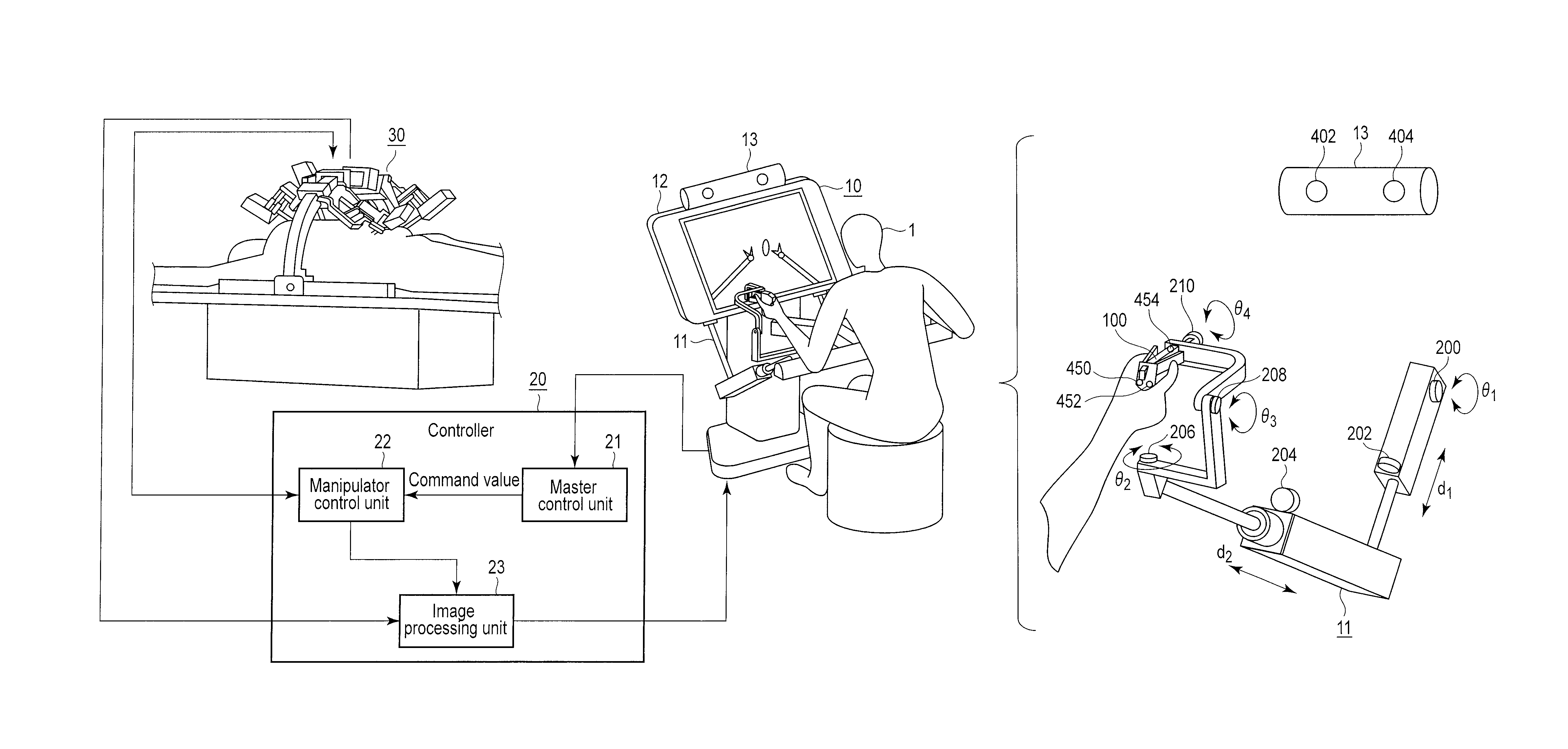
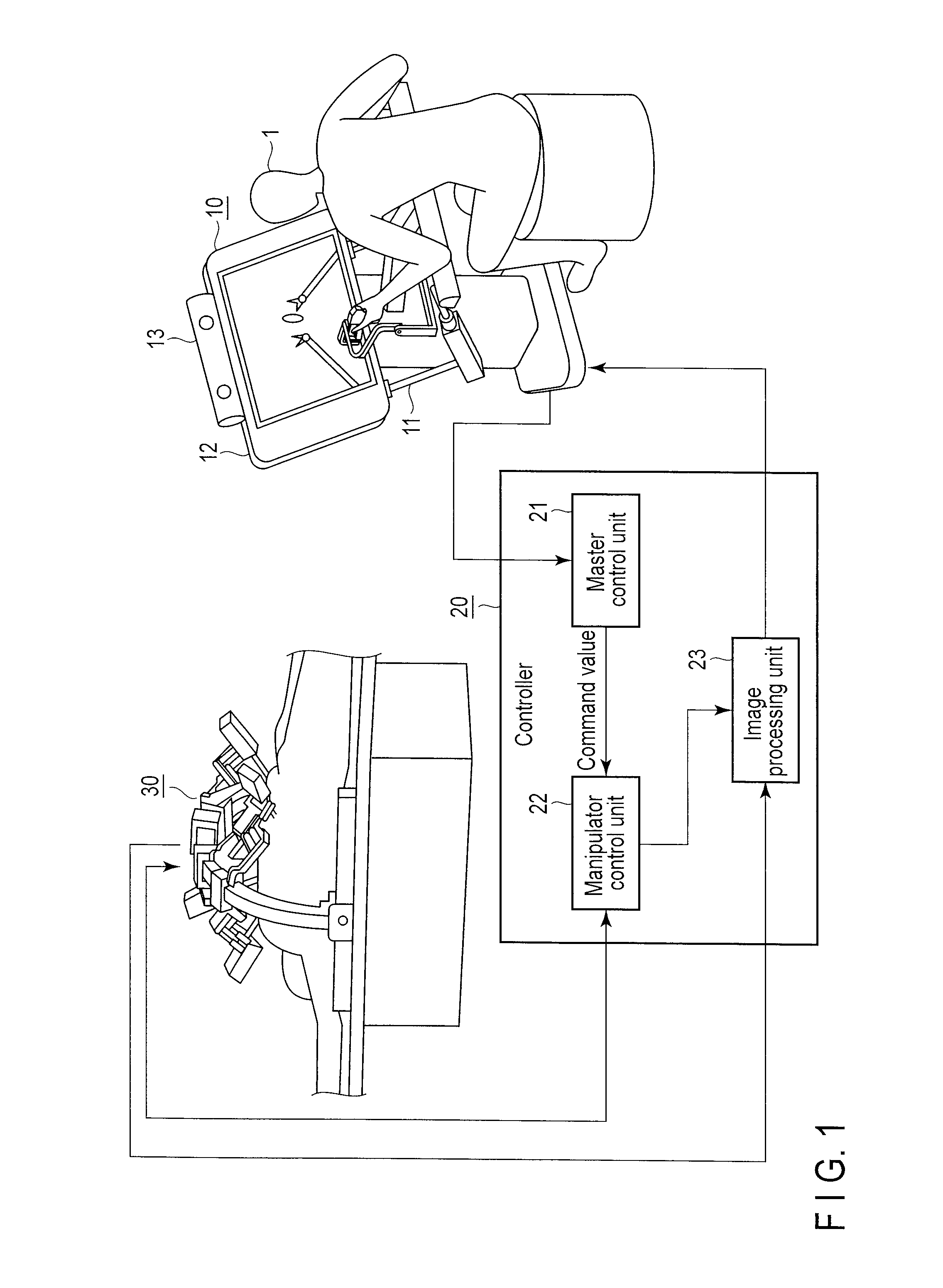
[0023]A first embodiment of the invention will be described first. FIG. 1 is a diagram showing an outline of an example of a master-slave manipulator according to the first embodiment of the invention. As shown in FIG. 1, the master-slave manipulator comprises a master input device 10, controller 20, and slave manipulator 30.

[0024]The master input device 10 comprises an input section 11, display section 12, and image sensor 13 and serves as a master of the master-slave manipulator.

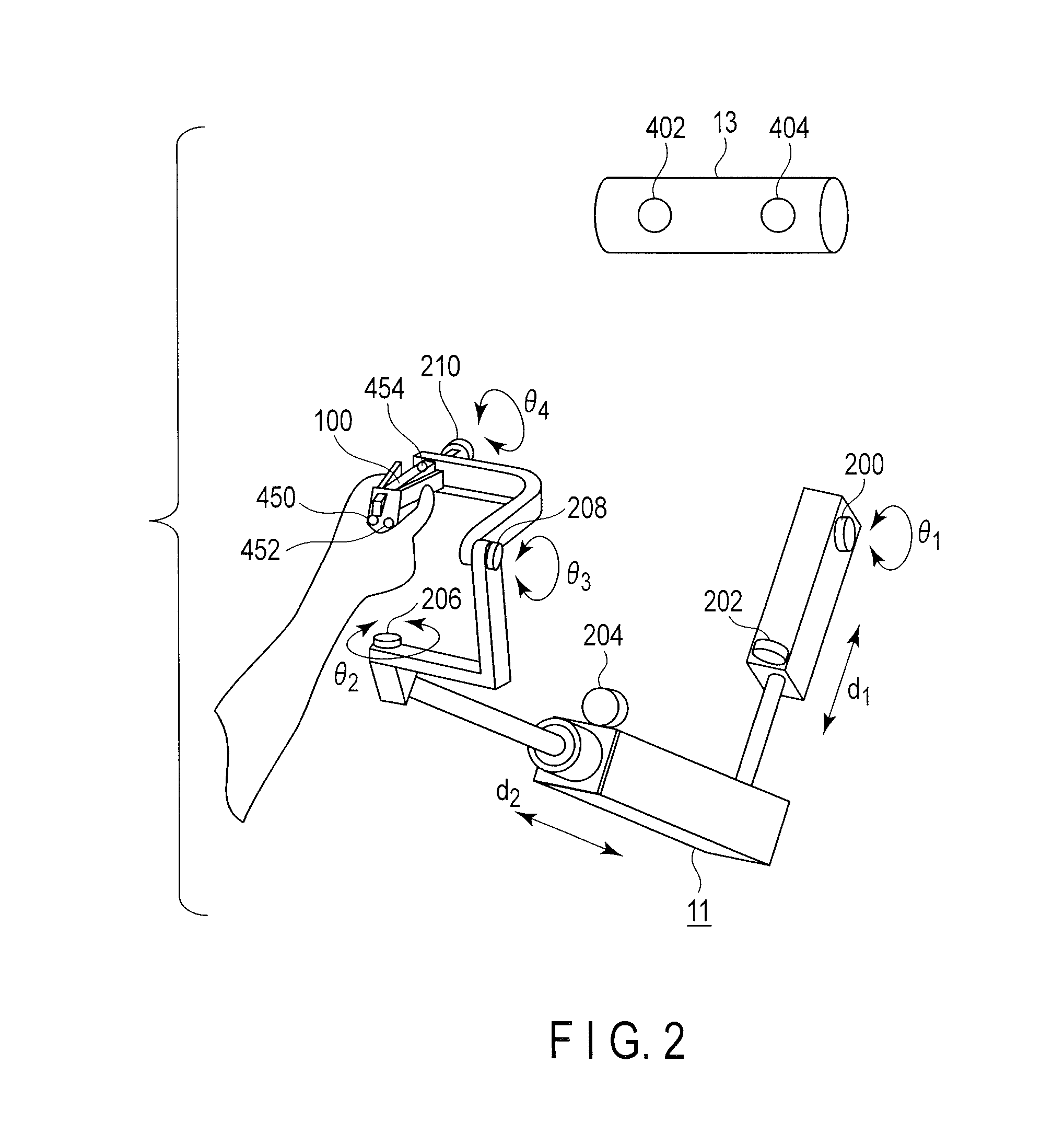
[0025]The input section 11 is fixed to, for example, the display section 12 of the master input device 10 and outputs a signal for actuating the slave manipulator 30 when it is operated by an operator 1. The input section 11 will be described in detail later.

[0026]The display section 12 comprises, for example, a liquid-crystal display and displays an image based on an image signal (described later) input from the controller 20. The input image signal is obtained by processing, in the controller 20, an imag...

second embodiment

[0058]The following is a description of a second embodiment of the invention. The second embodiment is an example in which a command value of the orientation of a grip unit 100 is determined as a command value B based on the output of a gyro sensor.

[0059]FIG. 5 is a view illustrating duplexing of sensors for detecting the position / orientation of an input section 11 of a master input device according to the present embodiment. A repeated description of like portions shown in FIGS. 2 and 5 is omitted. The configuration shown in FIG. 5 differs from that shown in FIG. 2 in that only a single marker 454 is disposed on a grip unit 100 and a gyro sensor 600 is attached to the grip unit 100.

[0060]The gyro sensor 600 is a three-axis sensor configured to output a signal corresponding to an angular speed produced in the grip unit 100 around X-, Y-, and Z-axes of a world coordinate system W. An amount of rotation as a variation of the orientation of the grip unit 100 is detected by integrating ...

third embodiment

[0070]The following is a description of a third embodiment of the invention. The third embodiment is an example in which command values of the position and orientation of a grip unit 100 are determined as a command value B from an acceleration sensor and gyro sensor, respectively.

[0071]FIG. 8 is a view illustrating duplexing of sensors for detecting the position / orientation of an input section 11 of a master input device according to the present embodiment. A repeated description of like portions shown in FIGS. 5 and 8 is omitted. The configuration shown in FIG. 8 differs from that shown in FIG. 5 in that a gyro sensor 600 and acceleration sensor 650 are arranged on the grip unit 100.

[0072]The acceleration sensor 650 is a three-axis sensor configured to output signals corresponding to accelerations individually parallel to X-, Y-, and Z-axes of a world coordinate system W. A displacement as a variation of the position of the grip unit 100 is detected by integrating the acceleration ...


PUM


Abstract

A master input device operates a slave manipulator which includes joints corresponding to a plurality of degrees of freedom. The device includes an operating unit and detection units of two or more systems. The operating unit is capable of being changed in position and orientation by an operator's operation. The operating unit is provided command values of a position and orientation of the slave manipulator as the position and orientation thereof change. The detection units individually detect different physical quantities related to the operating unit in order to detect the position and orientation of the operating unit.

Description

CROSS-REFERENCE TO RELATED APPLICATIONS[0001]This application is based upon and claims the benefit of priority from prior Japanese Patent Application No. 2011-038796, filed Feb. 24, 2011, the entire contents of which are incorporated herein by reference.BACKGROUND OF THE INVENTION[0002]1. Field of the Invention[0003]The present invention relates to a master input device for remotely operating a slave manipulator and a master-slave manipulator comprising the master input device.[0004]2. Description of the Related Art[0005]Robotic surgical treatment has recently been investigated to implement labor-saving medical facilities. In the field of surgery, various proposals are made for manipulator systems in which a manipulator with a multidegree-of freedom (or multi-joint) arm is used for the treatment of a patient. In one such known manipulator system (master-slave manipulator), the manipulator (slave manipulator) configured to directly contacts the patient's body cavity can be remotely o...

Claims


Application Information

Patent Timeline
Patent Type & Authority Patents(United States)
IPC IPC(8): G05B15/00B25J13/02G05B19/00B25J3/04A61B19/00
CPCB25J13/02A61B19/2203B25J3/04A61B19/56A61B2019/2223A61B2019/2269A61B2019/5255A61B2034/2055A61B34/25A61B34/30A61B34/37A61B34/74
Inventor OGAWA, RYOHEI
Owner OLYMPUS CORP
Why Eureka
Try Eureka