Connector terminal

a technology of connecting terminals and terminals, applied in the direction of coupling devices, two-part coupling devices, electrical devices, etc., can solve the problems of male terminals bending or damage the elastic contact plate b>1005/b>, and achieve the effect of high reliability of conta

Active Publication Date: 2015-11-17
DAIICHI SEIKO CO LTD
View PDF19 Cites 1 Cited by
  • Summary
  • Abstract
  • Description
  • Claims
  • Application Information

AI Technical Summary

Benefits of technology

[0015]In view of the above-mentioned problems in the conventional female terminals, it is an object of the present invention to provide a connector terminal capable of surely allowing a male terminal to make contact with an elastic contact plate of a female terminal to thereby provide highly reliable contact between male and female terminals.
[0017]In accordance with the above-mentioned connector terminal, the projection introduces a distal end of the contact piece to be located out of a cross-section of the insertion path. That is, even if the elastic contact piece attempts to float up at its distal end to thereby be located within a cross-section of the insertion path, the projection makes abutment with the distal end of the elastic contact piece to prevent the elastic contact piece from displacing. Thus, it is possible to prevent the distal end of the elastic contact piece from interfering with the male terminal.
[0021]By forming the projections on both of the inner walls of the sheath portion, the distal end of the elastic contact piece can make uniform contact at side edges thereof with the projections, ensuring it to prevent the elastic contact piece from displacing or floating up. That is, a pair of the projections prevents the elastic contact piece from displacing only at one of side edges.
[0026]Even if a user attempts to insert a jig into not the opening, but the sheath portion, an inner space of the sheath portion is narrowed by the projection, and accordingly, it is possible to prevent the user from inserting a jig wrongly into the sheath portion.
[0029]In accordance with the above-mentioned connector terminal, the projection makes contact with a distal end of the elastic contact piece to thereby prevent the elastic contact piece from displacing into an area corresponding to the insertion path. Accordingly, the elastic contact piece does not interfere at a distal end thereof with a male terminal having been inserted into the sheath portion. Thus, the male terminal is able to surely make mechanical and electrical contact with the elastic contact piece to thereby provide highly reliable electrical connection between the male terminal and the connector terminal.

Problems solved by technology

If the male terminal is inserted into the sheath portion 1101 while the elastic contact plate 1005 is floating up at the front edge thereof, the male terminal makes contact with and pushes the front edge, resulting in that it is afraid that the elastic contact plate 1005 may be bent or damaged by the male terminal.

Method used


Image

  • Connector terminal
  • Connector terminal
  • Connector terminal

Examples


Embodiment Construction

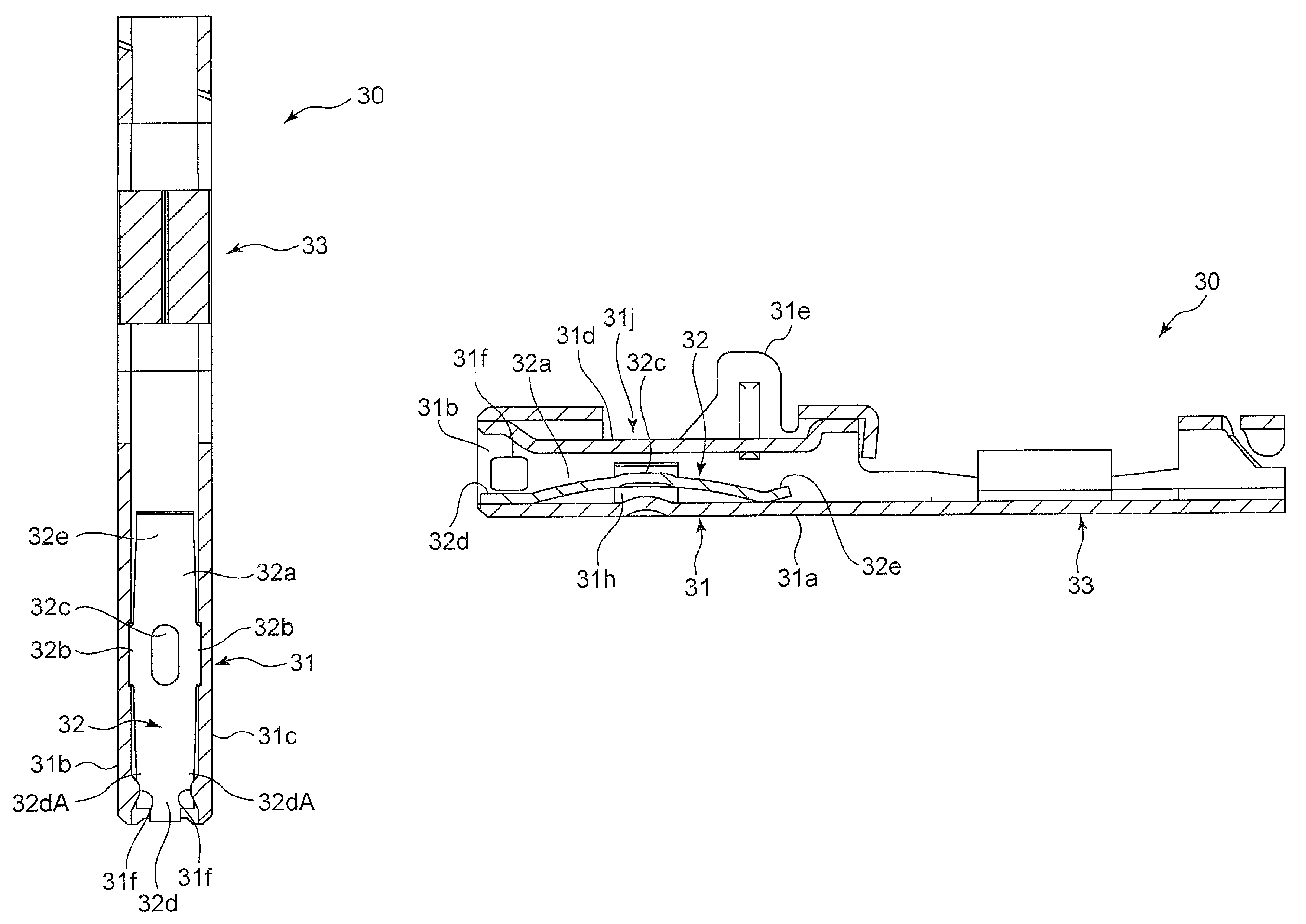
[0047]A connector terminal in accordance with the preferred embodiment of the present invention and an electric connector employing the connector terminal are explained hereinbelow with reference to drawings. In the specification, a wording “front” or “forward” refers to a direction in which the connector terminal is inserted into a housing (that is, a direction X illustrated in FIG. 1), and a wording “rear” or “backward” refers to the opposite direction.

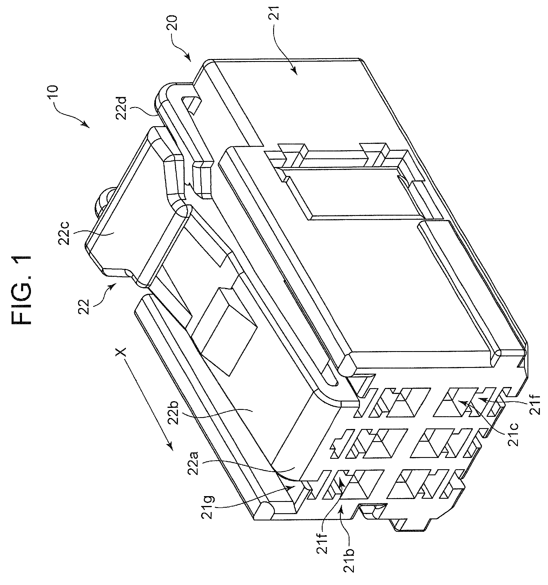
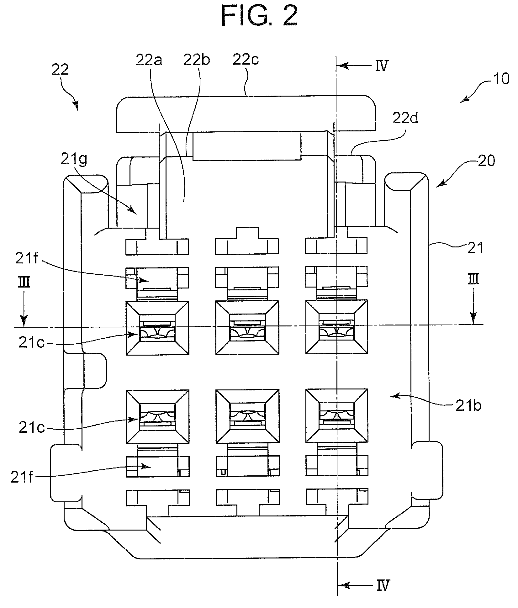
[0048]An electric connector 10 illustrated in FIGS. 1 to 4 is a female connector into which a male connector C (see FIG. 11) including male terminals P each in the form of a needle is inserted.

[0049]The electric connector 10 includes a housing 20 formed by a molding injection process, and a plurality of female connector terminals 30 in accordance with the preferred embodiment of the present invention. Each of the male terminals P of the male connector C is inserted into the corresponding connector terminal 30 to thereby make electri...


PUM


Abstract

A connector terminal includes a hollow sheath portion to be inserted into a terminal space formed in a housing of an electric connector, and an elastic contact piece positioned in the sheath portion, the contact piece making mechanical and electrical contact with a male terminal of an opponent electric terminal when the male terminal is inserted into the sheath portion, the male terminal being inserted into the sheath portion through an insertion path formed in the housing, the sheath portion being formed with a projection on at least one of inner walls thereof facing each other, the projection introducing a distal end of the contact piece to be located out of a cross-section of the insertion path in a direction perpendicular to a direction in which the male terminal is inserted into the sheath portion.

Description

BACKGROUND OF THE INVENTION[0001]1. Field of the Invention[0002]The invention relates to a connector terminal including a hollow sheath portion to be inserted into a terminal space formed in a housing of an electric connector, and an elastic contact piece positioned in the sheath portion to make mechanical and electrical contact with a male terminal of an opponent electric terminal when the male terminal is inserted into the sheath portion.[0003]2. Description of the Related Art[0004]There is known a female connector terminal to be inserted into a terminal space formed in a connector housing to make mechanical and electrical contact with a male terminal of an opponent connector when the male terminal is inserted into the terminal space.[0005]FIG. 15 is a perspective view of an example of such a female connector terminal, suggested in Japanese Patent Application Publication No. 2001-52791.[0006]A female terminal 1000 illustrated in FIG. 15 includes a sheath portion 1001 and an elasti...

Claims


Application Information

Patent Timeline
Patent Type & Authority Patents(United States)
IPC IPC(8): H01R13/187H01R13/424H01R13/629H01R24/76
CPCH01R13/424H01R13/187H01R13/629H01R24/76H01R4/185H01R13/113
Inventor ENDO, TAKAYOSHIYAGI, SAKAITAKEDA, TAKUYA
Owner DAIICHI SEIKO CO LTD
Why Eureka
Try Eureka