Unlock instant, AI-driven research and patent intelligence for your innovation.

Stereoscopic projection device and display method thereof

a projection device and projection device technology, applied in the direction of picture reproducers, picture reproducers using projection devices, instruments, etc., can solve the problems of large overall size, high display cost, and inverse proportionality of display efficiency to the number

Active Publication Date: 2015-11-17
DELTA ELECTRONICS INC
View PDF4 Cites 0 Cited by
  • Summary
  • Abstract
  • Description
  • Claims
  • Application Information

AI Technical Summary

Benefits of technology

The present invention is about a device that can show two different images simultaneously on a screen. This makes it possible to create a 3D impression for the viewer. The device is made up of a special light projector and a special light system that splits and combines the light beams. This makes it easy to show multiple images on a screen and create a realistic 3D effect.

Problems solved by technology

However, since a plurality of such projectors are used to provide an image in a conventional autostereoscopic display, this results in an overall large size and high cost for the display.
Moreover, in the slit switch light field technology, images in non-working views must be blocked, resulting in the efficiency of the display being inversely proportional to the number of the views.
Therefore, a large size of the autostereoscopic display is hard to achieve due to the unexpected loss of brightness.

Method used


Image

  • Stereoscopic projection device and display method thereof
  • Stereoscopic projection device and display method thereof
  • Stereoscopic projection device and display method thereof

Examples


Embodiment Construction

[0042]In the following detailed description, for purposes of explanation, numerous specific details are set forth in order to provide a thorough understanding of the disclosed embodiments. It will be apparent, however, that one or more embodiments may be practiced without these specific details. In other instances, well-known structures and devices are schematically depicted in order to simplify the drawings.

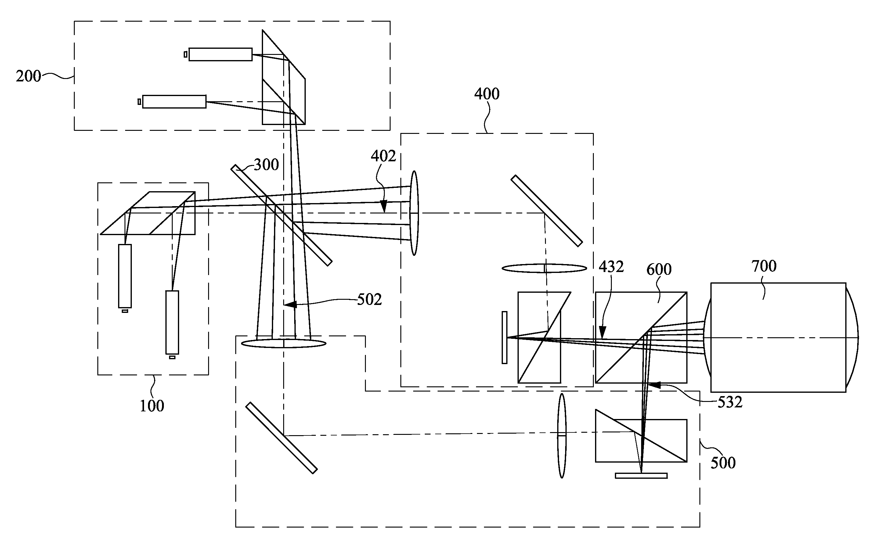
[0043]FIG. 1 is a schematic diagram of a stereoscopic projection device according to one embodiment of the present invention. The stereoscopic projection device includes a first light source module 100, a second light source module 200, a dichroic mirror 300, a first optical module 400, a second optical module 500, and a beam-combining prism 600. Each of the first light source module 100 and the second light source module 200 includes a plurality of light sources which provide light beams, respectively. The light beams of the first light source module 100 propagate at different ...


PUM


Abstract

A stereoscopic projection device includes a plurality of light source modules, a dichroic mirror, a first optical module, a second optical module, and a beam-combining prism. Each light source module includes a plurality of light sources used for providing light beams and a prism module used for collecting the light beams. The light beams propagate at different angles after passing through the prism module. The light source modules are disposed on different sides of the dichroic mirror. The dichroic mirror is used for guiding portions of the light beams to a first optical path, and guiding other portions of the light beams to a second optical path. The first and second optical modules disposed on the first and second optical path are used for guiding and modulating the light beams passing along the first and second optical paths and forming first and second image light beams with different images.

Description

RELATED APPLICATIONS[0001]This application claims priority to Taiwan Application Serial Number 101150855, filed Dec. 28, 2012, which is herein incorporated by reference.BACKGROUND[0002]1. Technical Field[0003]The present disclosure relates to a stereoscopic projection device.[0004]2. Description of Related Art[0005]Exploiting the binocular parallax of humans, a stereoscopic display provides two different images respectively to the two eyes of an observer, such that the observer can experience a stereoscopic image. Unlike other kinds of stereoscopic displays which require the use of special glasses to distinguish between left-eye and right-eye images, the autostereoscopic display provides a plurality of images by using a plurality of light sources, in which the images are projected to different spatial positions. The eyes of an observer can receive different images such that the observer perceives a stereoscopic image when his or her eyes correspond to any two of the spatial position...

Claims


Application Information

Patent Timeline
Patent Type & Authority Patents(United States)
IPC IPC(8): H04N13/04H04N9/31G02B30/25G03B35/00H04N13/363
CPCH04N13/0459H04N9/3111H04N13/0438H04N13/341H04N13/363
Inventor WANG, YU-CHANG
Owner DELTA ELECTRONICS INC