Check patentability & draft patents in minutes with Patsnap Eureka AI!

Communication system, receiving device, relay device, reception method, and relay method

a communication system and relay technology, applied in the field of packet communication system, can solve the problems of specific problems of wireless network, and low reliability of wireless network link ra

Inactive Publication Date: 2015-11-24
FUJITSU LTD
View PDF25 Cites 3 Cited by
  • Summary
  • Abstract
  • Description
  • Claims
  • Application Information

AI Technical Summary

Benefits of technology

The patent text describes a receiving device that can receive packets through multiple paths. The device generates a message to confirm that it received a packet on one of the paths and sends it to a different path. This allows for more efficient processing and faster data transfer. The technical effect of this invention is improved data transmission speed and reliability.

Problems solved by technology

In general, however, a wireless network has specific problems.
Specifically, the wireless network has lower reliability than a wired network and a link rate of the wireless network is not constant.
When the link rate is reduced, a packet is easily delayed or lost owing to overflow of a buffer with packets that are not transmitted.
As described above, a failure easily occurs in a wireless network, compared with a wired network.
However, a utilization that is calculated from a failure rate of a network device is lower than a utilization to be guaranteed in many cases.
In addition, in a trunk over which data from multiple users is multiplexed, when a failure occurs in a single part of a network system, communication of a lot of users is affected by the failure.
However, when a wireless network is redundant in a simple manner, the following problem remains.
It is assumed that a wireless environment of one of redundant paths provided in a redundant wireless network becomes worse.
Specifically, it is assumed that relay devices are sufficiently separated from each other and the wireless environment of only the one of the redundant paths becomes worse owing to the weather or the like, as illustrated in FIG. 2.
Based on this assumption, the rate of only one of wireless links is easily reduced, and a packet is easily delayed or lost in the one of the wireless links.
Thus, a packet that is the same as a packet that has been already received by a receiving device over the other wireless link may be significantly delayed and received from a node located on the path whose wireless environment is worse.
Therefore, transmission of the packet that is the same as the packet already received by the receiving device leads to waste of a wireless resource and is not preferable.
When the link rate is reduced, a delay of transfer of a packet or a delay of buffering a packet increases in the communication path in which the quality of the wireless link is reduced.
Thus, a relay device that is located on the communication path in which the quality of the wireless link is reduced may delay transfer of a packet and transfer the packet that does not need to be transferred since the same packet has been received by the receiving device over the other communication path.
The transfer of the packet is waste of the wireless resource.
This may cause a loss of the packet.
The same problem occurs not only when the link rate is reduced, but also when one of the plurality of paths that connect the receiving device to the transmitting device is much longer than the other path.
It is highly likely that reception of a packet that is transferred over the longer path is delayed, compared with a packet that is transferred over the shorter path.
The transfer of this packet leads to waste of the wireless resource.
However, since the links are wireless, it is inevitable that a certain percentage of packets are lost.
Thus, it is not realistic to transfer a packet only over the path whose link rate is higher than the other path.

Method used


Image

  • Communication system, receiving device, relay device, reception method, and relay method
  • Communication system, receiving device, relay device, reception method, and relay method
  • Communication system, receiving device, relay device, reception method, and relay method

Examples


first embodiment

[0054]A first embodiment is described with reference to FIGS. 3 to 19.

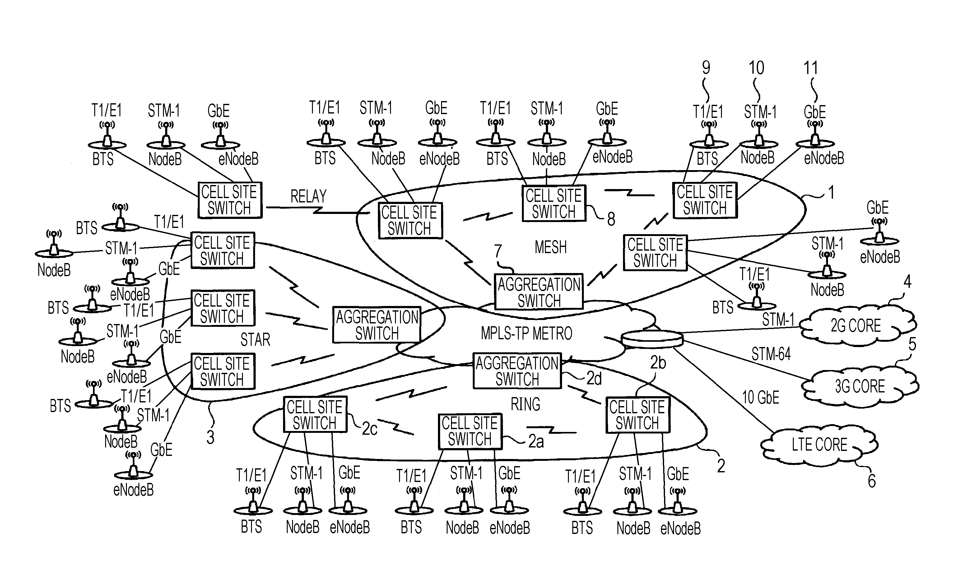
[0055]FIG. 3 is a diagram illustrating an entire network that includes a receiving device and relay devices according to the first embodiment. In the single physical network, a plurality of networks logically exist. In addition, a 2G core, a 3G core and a LTE core are logical networks and described later. Networks other than the logical networks are physical networks. The configuration of the network illustrated in FIG. 3 may be achieved by a technique such as an ATM technique or a virtual local area network (VLAN) using Ethernet.

[0056]In the configuration of the network illustrated in FIG. 3, the receiving device and the relay devices according to the present embodiment may be configured in a ring topology and a mesh topology. For example, if the ring topology is used and a cell site switch 2a is a transmitting device according to the present embodiment, the relay devices are a cell site switch 2b and a cell site...

second embodiment

[0142]Flows of processes to be performed by the reception-acknowledgement information generator 65 are described with reference to FIGS. 20 to 22.

[0143]FIG. 20 illustrates a reception-acknowledgement information management table according to the second embodiment.

[0144]As illustrated in FIG. 20, the reception-acknowledgement information management table 170 stores a flow ID 171, a consecutive reception acknowledgement sequence number 172 and a selection reception acknowledgement bitmap 173, while the flow ID 171, the consecutive reception acknowledgement sequence number 172 and the selection reception acknowledgement bitmap 173 are associated with each other.

[0145]The consecutive reception acknowledgement sequence number 172 indicates that packets that have sequence numbers that are equal to or smaller than the consecutive reception acknowledgement sequence number 172 have been received by the receiving device 23.

[0146]The selection reception acknowledgement bitmap 173 has a most s...

third embodiment

[0166]The flow of a process that is performed by the controller 75 of the relay device 22 is described with reference to FIG. 27.

[0167]The controller 75 receives the reception-acknowledgement information from the reception-acknowledgement information receiver 74 (in operation 231) and acquires, from the reception-acknowledgement information, a sequence number added to the packet completely received by the receiving device 23 (in operation 232).

[0168]The controller 75 compares the acquired sequence number with the maximum sequence number of packets that are stored in the buffer memory 72 and correspond to an interested flow (in operation 233).

[0169]As a result of the comparison made in operation 233, when the acquired sequence number is larger than the maximum sequence number, the controller 75 discards a packet that has a smaller sequence number than the acquired sequence number (in operation 234). Then, the controller 75 updates a reception acknowledgement sequence number 132 that...


PUM


Abstract

A receiving device includes a packet receiver that is coupled to a plurality of paths, and a packet transmitter that generates reception-acknowledgement information indicating that the packet receiver receives a packet when the packet receiver receives the packet over one of the paths, and that transmits the reception-acknowledgement information to a path that is among the plurality of paths and different from the path over which the packet receiver has received the packet.

Description

CROSS-REFERENCE TO RELATED APPLICATION[0001]This application is based upon and claims the benefit of priority of the prior Japanese Patent Application No. 2011-014922, filed on Jan. 27, 2011, the entire contents of which are incorporated herein by reference.FIELD[0002]The embodiments discussed herein are related to a packet communication system.BACKGROUND[0003]In recent years, there has been an increase in the number of cases in which a wireless technique is applied to a backhaul or the like that connects a base station of a mobile phone network to a core network so that an entire network is quickly built at low cost. In general, however, a wireless network has specific problems. Specifically, the wireless network has lower reliability than a wired network and a link rate of the wireless network is not constant.[0004]For example, the rate of a wireless link may be dynamically changed by changing a modulation scheme and / or a coding rate based on a change in a wireless environment in ...

Claims


Application Information

Patent Timeline
Patent Type & Authority Patents(United States)
IPC IPC(8): H04W28/06H04L1/18H04L1/00H04L1/16H04W84/04H04L45/243H04L45/586H04W16/26H04W24/04H04W40/00
CPCH04W28/06H04L1/1835H04L2001/0097H04L1/1614H04W84/047
Inventor OKUDA, MASATO
Owner FUJITSU LTD
Features
  • R&D
  • Intellectual Property
  • Life Sciences
  • Materials
  • Tech Scout
  • Unparalleled Data Quality
  • Higher Quality Content
  • 60% Fewer Hallucinations
Learn More