
Method for producing glass substrate and glass substrate

a technology of glass substrate and glass substrate, which is applied in the field of glass substrate, can solve the problems of reducing the surface quality of the substrate and difficulty in making the sheet thin, and achieve the effect of excellent surface quality and small sheet thickness

Active Publication Date: 2015-12-01
NIPPON ELECTRIC GLASS CO LTD
View PDF22 Cites 2 Cited by
  • Summary
  • Abstract
  • Description
  • Claims
  • Application Information

AI Technical Summary

Benefits of technology

The present invention relates to a method for regulating the cooling rate of a glass panel in a temperature region above the annealing point, which results in a glass substrate with small warping and residual stress. By controlling the cooling rate, the time for subsequent annealing is secured, allowing for a small thermal shrinkage ratio. The method also allows for easy selection of a glass composition suitable for display substrates, including chemical resistance, specific modulus, and meltability. Additionally, the glass has excellent surface quality without requiring polishing. Overall, this method achieves the objective of thin and bendable flexible displays with high strain point and low thermal shrinkage ratio.

Problems solved by technology

However, the float method involves such disadvantages that it is difficult to make the sheet thin, the glass substrate is required to be polished to remove tin attached onto the glass surface, and the surface quality of the substrate is lowered.

Method used


Image

  • Method for producing glass substrate and glass substrate
  • Method for producing glass substrate and glass substrate
  • Method for producing glass substrate and glass substrate

Examples


examples

[0067]The present invention is hereunder described in detail by reference to the accompanying drawings.

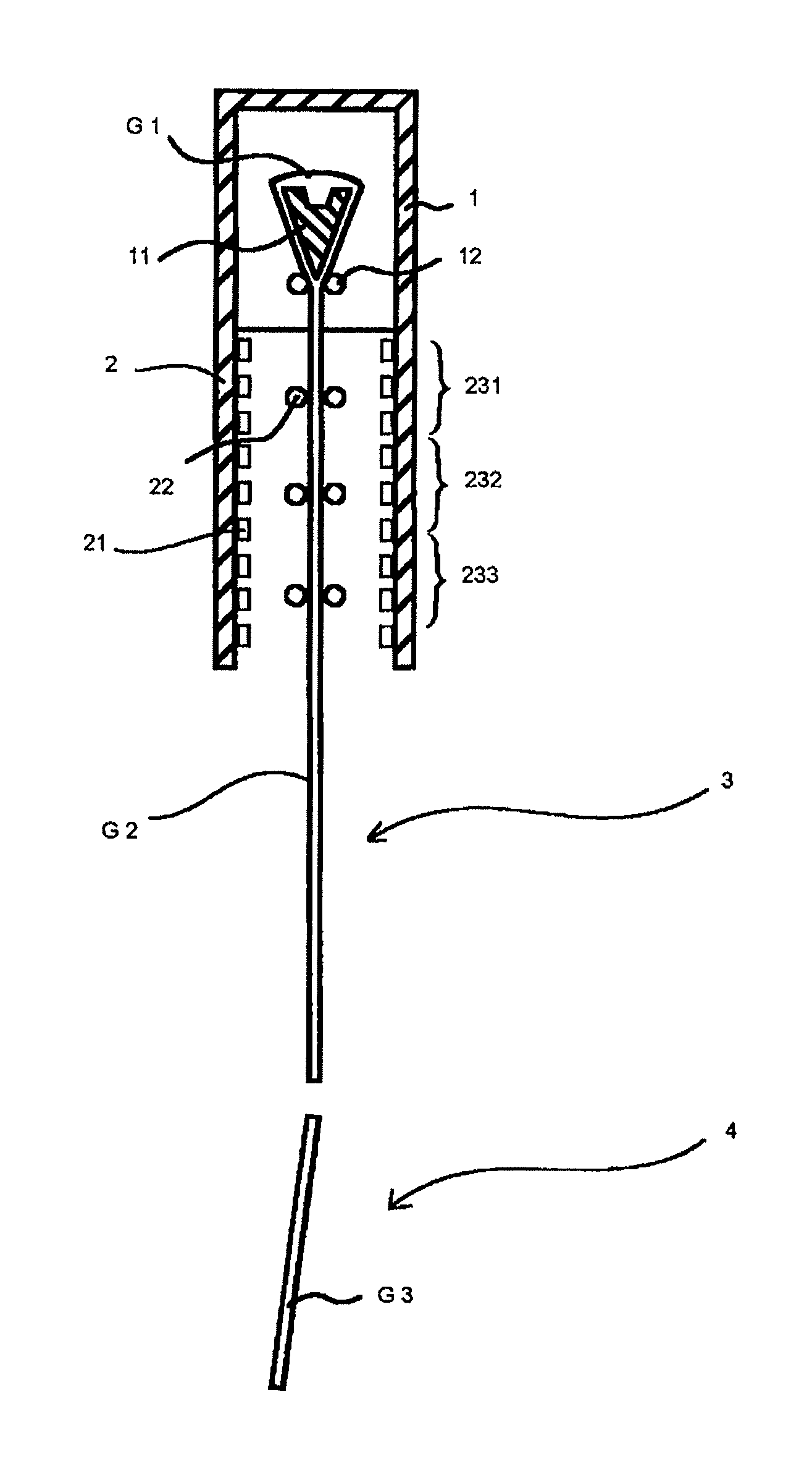
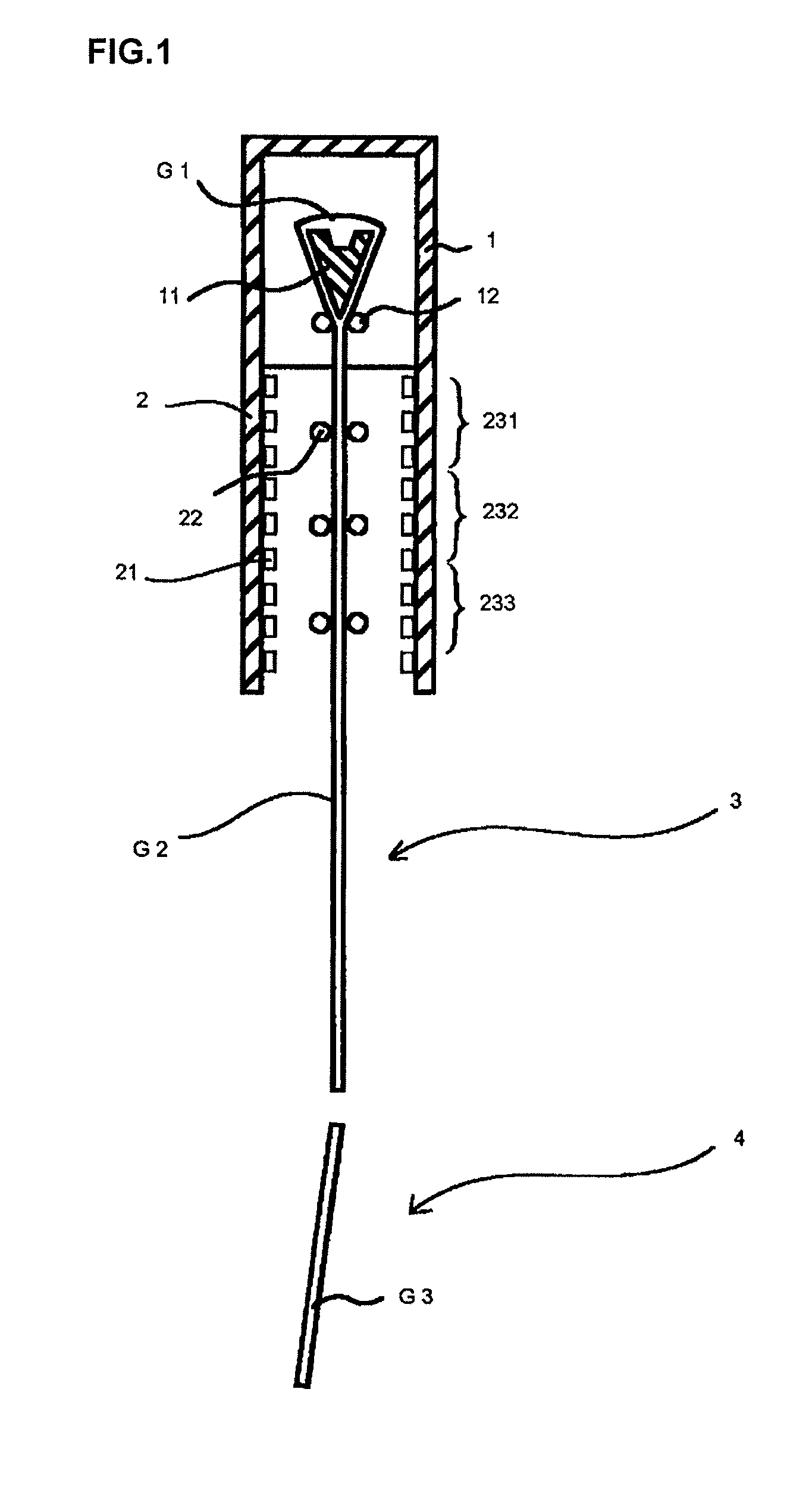
[0068]FIG. 1 is an outline front view showing production equipment for a glass substrate in carrying out the present invention. The production equipment is for producing a glass substrate according to an overflow down draw method, and it includes a forming furnace 1 having a trough-shaped forming body 11 and cooling rollers 12 therein in this order from the top thereof; an annealing furnace 2 disposed in a lower portion of the forming furnace 1 and having heaters 21 and guide rollers 22 therein; and a cooling section 3 and a cutting section 4 provided in a lower portion of the annealing furnace 2.

[0069]The trough-shaped forming body 11 has a nearly wedge-shaped cross section and allows a molten glass G1 to be fed to overflow out from the top thereof and fuse at the bottom thereof to form a glass ribbon G2. The annealing furnace 2 anneals the glass ribbon G2. In detail, in the insid...


PUM

PropertyMeasurementUnit
thicknessaaaaaaaaaa
temperatureaaaaaaaaaa
thicknessaaaaaaaaaa

Abstract

The present invention is aimed to provide a method for producing a glass substrate with a thickness of not more than 200 μm, which is satisfied with the quality required for a substrate on which a thin-film electric circuit is formed, and a sheet glass substrate obtained according to this method. The present invention is concerned with a method for producing a glass substrate having a sheet thickness of from 10 to 200 μm, including a forming step of forming a molten glass into a ribbon shape in accordance with a down draw method, an annealing step of annealing the glass ribbon, and a cutting step of cutting the glass ribbon to give a glass substrate, wherein an average cooling rate in a temperature range of from the (annealing point+200° C.) to the (annealing point+50° C.) is controlled to the range of from 300 to 2,500° C. / min.

Description

TECHNICAL FIELD[0001]The present invention relates to a glass substrate on which a thin-film electric circuit is formed, in particular to a glass substrate which is used for flat panel displays and flexible displays such as liquid crystal displays, organic EL displays, and the like.BACKGROUND ART[0002]Glass substrates which are used for a display application are generally formed according to a float method, a down draw method represented by an overflow down draw method, or the like.[0003]The float method is a method of casting a molten glass onto molten tin (float bath) and stretching it in the horizontal direction to form the glass in a sheet form. According to the method, a glass ribbon is formed on the float bath, and the glass ribbon is then annealed (on-line annealed) in a long annealing furnace. Accordingly, the glass substrate formed according to the float method is characterized by having a small thermal shrinkage ratio.[0004]However, the float method involves such disadvant...

Claims


Application Information

Patent Timeline
Patent Type & Authority Patents(United States)
IPC IPC(8): C03B17/06C03C3/091C03B25/00
CPCC03B17/067C03C3/091Y10T428/24355C03B25/08C03C3/089Y02P40/57
Inventor KAWAGUCHI, TAKAHIROFUJIWARA, KATSUTOSHIKATO, YOSHINARIAIBA, HISATOSHI
Owner NIPPON ELECTRIC GLASS CO LTD
Learn More