Power supply device and driving method thereof

a technology of power supply device and driving method, which is applied in the direction of transformers, inductances, transportation and packaging, etc., can solve the problems of low operation speed, inability to withstand long-term use, and large power consumption in position detection operation, so as to reduce power consumption, high reliability of power supply, and withstand long-term use

Active Publication Date: 2015-12-01
SEMICON ENERGY LAB CO LTD
View PDF159 Cites 4 Cited by
  • Summary
  • Abstract
  • Description
  • Claims
  • Application Information

AI Technical Summary

Benefits of technology

[0012]An object of one embodiment of the present invention is to provide a highly reliable power supply device which can withstand long-term use.
[0013]Another object of one embodiment of the present invention is to provide a power supply device with high productivity.
[0014]Another object of one embodiment of the present invention is to provide a power supply device with reduced power consumption.
[0025]A highly reliable power supply device which can withstand long-term use can be provided. A power supply device with reduced power consumption can be provided.

Problems solved by technology

A mechanical switch manufactured using a micro electro mechanical system (MEMS) technology is used as the power feeding switch because high voltage and a large amount of current need to flow; however, there are problems in that it has a low operation speed and cannot withstand long-term use because of its poor durability.
However, an OFET has a high drive voltage of several tens of voltage and thus consumes much power in position detection operation.
Since the power feeding switch and the position detecting switch satisfy different required specifications, they need to be formed separately; thus, manufacturing steps become complicated.
Since high-frequency waves with different frequencies are used as a high-frequency wave for supplying power and a high-frequency wave for detecting a position, a high-frequency wave supply circuit for supplying power and a high-frequency wave supply circuit for detecting a position need to be provided separately, whereby a circuit configuration becomes complicated.
Therefore, the number of components is increased, and improvement in productivity and cost reduction are difficult to achieve.

Method used


Image

  • Power supply device and driving method thereof
  • Power supply device and driving method thereof
  • Power supply device and driving method thereof

Examples


embodiment 1

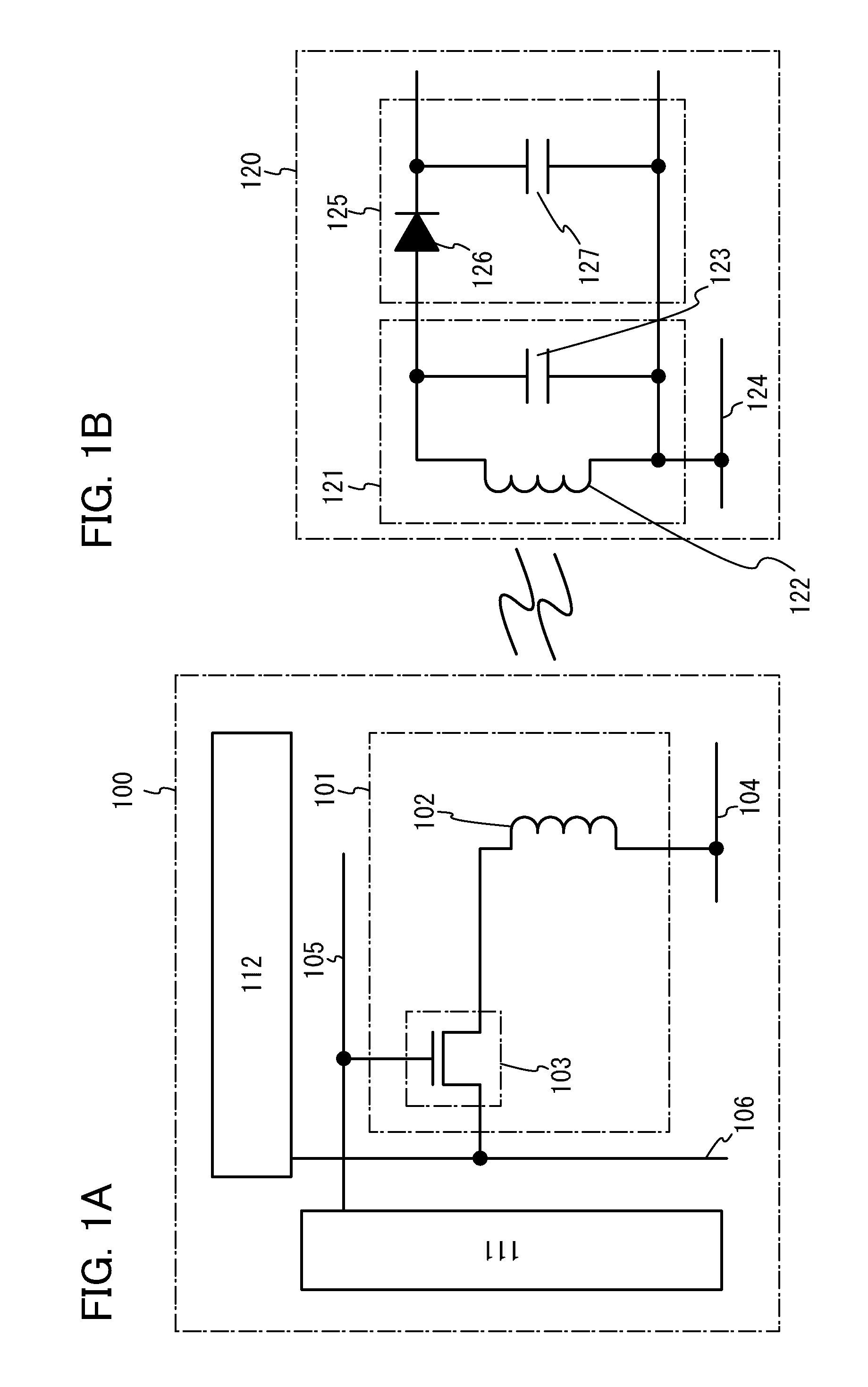
[0043]In this embodiment, an example of a power supply device which is one embodiment of the present invention will be described with reference to FIGS. 1A and 1B.

[0044]A power supply device 100 illustrated in FIG. 1A includes a power feeding switch control circuit 111, a high-frequency wave supply circuit 112, and at least one power feeding cell 101. The power feeding cell 101 includes a power feeding antenna 102 and a power feeding switch 103. For the power feeding switch 103, a transistor including an oxide semiconductor in a channel formation region is used. The power feeding switch 103 functions as a switch for controlling supply of a high-frequency wave to the power feeding antenna 102. One electrode (terminal) of a source electrode and a drain electrode of the power feeding switch 103 is connected to a wiring 106, and a gate electrode (control terminal) of the power feeding switch 103 is connected to a wiring 105. Further, the other electrode (terminal) of the source electrod...

embodiment 2

[0059]In this embodiment, a position detecting device which can be used for a power supply device of one embodiment of the present invention will be described. By using the position detecting device, whether there is a power receiving device or not can be detected.

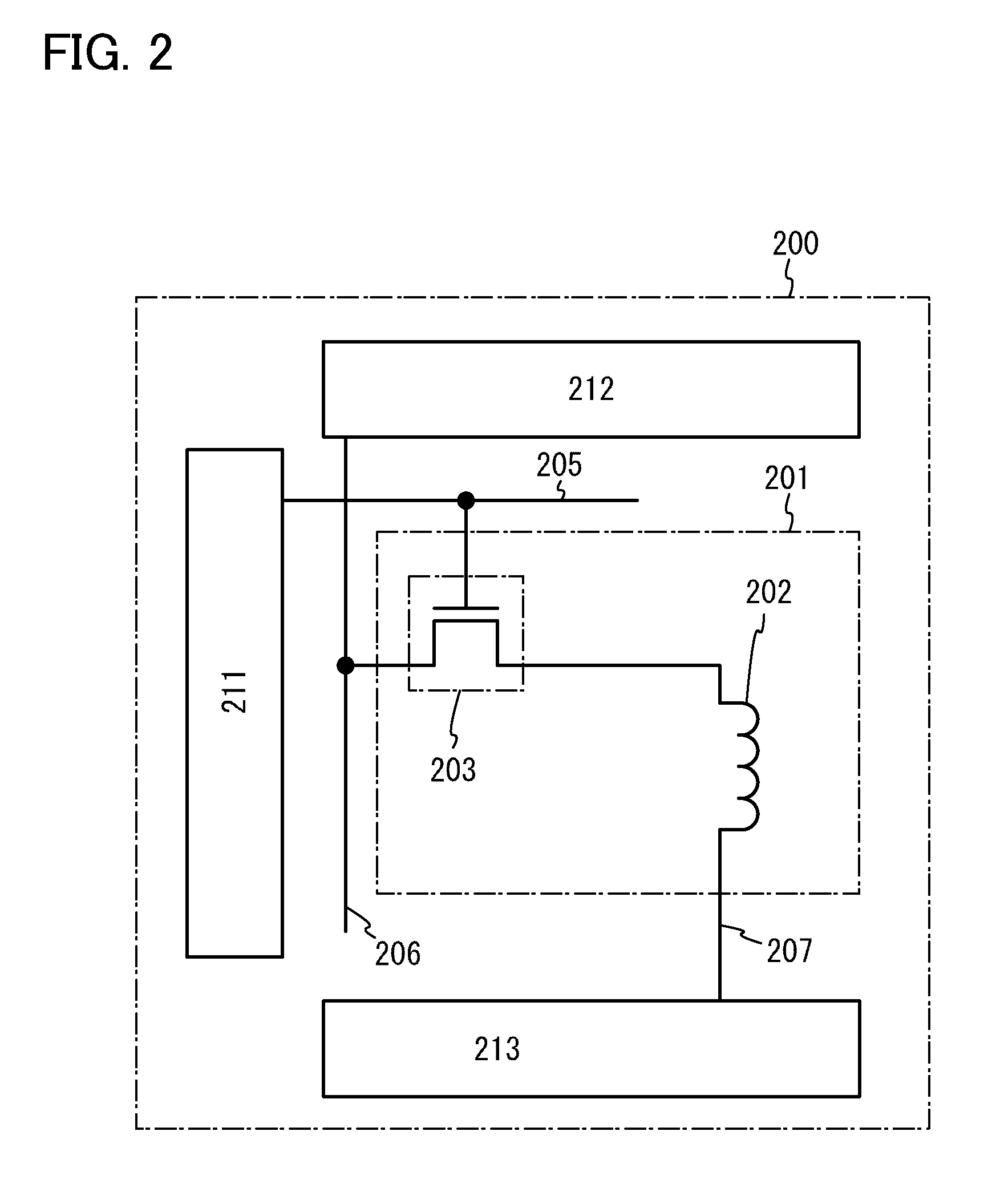
[0060]A position detecting device 200 illustrated in FIG. 2 includes a position detecting switch control circuit 211, a high-frequency wave supply circuit 212, and at least one position detecting cell 201. The position detecting cell 201 includes a position detecting antenna 202 and a position detecting switch 203. As the position detecting switch 203, a transistor including an oxide semiconductor in a channel formation region is used. The position detecting switch 203 functions as a switch for controlling supply of a high-frequency wave to the position detecting antenna 202. One electrode (terminal) of a source electrode and a drain electrode of the position detecting switch 203 is connected to a wiring 206, and a gate el...

embodiment 3

[0074]In this embodiment, an example is described in which the power feeding switches and the position detecting switches which are described in Embodiments 1 and 2 are arranged in a matrix. The power feeding cells and / or the position detecting cells are arranged in a matrix to form an antenna sheet.

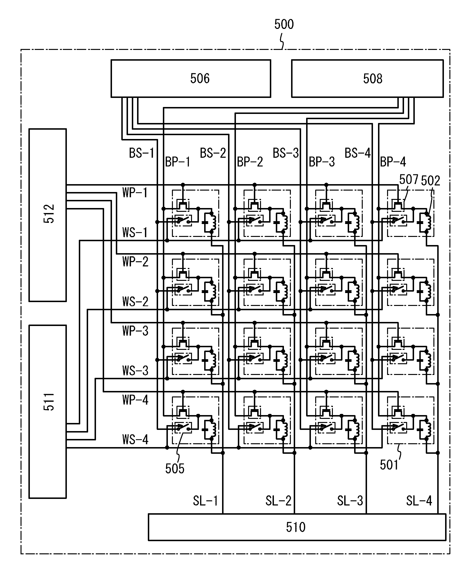
[0075]First, a structure of a conventional power supply device 500 and operation thereof are described with reference to FIGS. 3A and 3B. The conventional power supply device 500 illustrated in FIG. 3A includes a power feeding cell 501, a first high-frequency wave supply circuit 506, a second high-frequency wave supply circuit 508, a power feeding switch control circuit 511, a position detecting switch control circuit 512, and a potential detecting circuit 510.

[0076]The power feeding cell 501 has a coiled antenna 502 which is used for both power feeding and position detection. One electrode of the antenna 502 is connected to the first high-frequency wave supply circuit 506 for the power ...


PUM

PropertyMeasurementUnit
frequencyaaaaaaaaaa
frequencyaaaaaaaaaa
frequenciesaaaaaaaaaa

Abstract

An object of the present invention is to provide a highly reliable power supply device which can withstand long-term use. Another object of the present invention is to provide a power supply device with reduced power consumption. The power supply device includes a cell including an antenna and a switch and performing position detection operation and power feeding operation; a high-frequency wave supply circuit; a switch control circuit; and a potential detecting circuit. One electrode of the antenna is connected to the high-frequency wave supply circuit through the switch, and the other thereof is connected to the potential detecting circuit. By the position detection operation, whether there is a power receiving device which gets close to a cell or not is detected. Only when the power receiving device is detected, power is supplied by the power feeding operation.

Description

TECHNICAL FIELD[0001]The present invention relates to a power supply device. In particular, the present invention relates to a power supply device which supplies power by a radio signal.[0002]In this specification, a semiconductor device means all types of devices which can function by utilizing semiconductor characteristics, and an imaging device, a display device, an electro-optical device, a power supply device, a semiconductor circuit, an electronic device, and the like are all semiconductor devices.BACKGROUND ART[0003]In recent years, with the development of information communication technology, the realization of a ubiquitous society is proposed in which free communication of information and a variety of services can be achieved by connecting a variety of electronic devices to a computer network. The word “ubiquitous” comes from the Latin meaning “existing or being everywhere” (being omnipresent) and means that the processing of information using computers is naturally widespr...

Claims


Application Information

Patent Timeline
Patent Type & Authority Patents(United States)
IPC IPC(8): H01F38/14H04B5/00H02J5/00H02J7/02
CPCH04B5/0093H02J5/005H04B5/0037H02J7/025H01F38/14H02J50/402H02J50/90H02J50/12H02J50/20H02J50/40H02J50/005H02J50/23
Inventor SAITO, TOSHIHIKO
Owner SEMICON ENERGY LAB CO LTD
Why Eureka
Try Eureka