Adhesive tape cutter

Inactive Publication Date: 2005-03-17
KTF
View PDF4 Cites 1 Cited by
  • Summary
  • Abstract
  • Description
  • Claims
  • Application Information

AI Technical Summary

Benefits of technology

[0009] The present invention is an adhesive tape cutter intended to solve the problems described above, and its object is to provide an adhesive tape cutter wherein: the cutting blade is circular in shape and contact location for cutting is a partial arc of roughly 90°, so when the tape is lowered from above, cutting is possible from the center and even if a twist to the left o

Problems solved by technology

Conventional adhesive tape cutters use saw tooth-shaped cutting blades that are serrated and so do not cut well, and also the cut edge of the tape is also serrated in shape, and thus they have drawbacks in that when tape is applied to the desired area, the clean appearance of a product or item to be adhered to may be lost.
However, even though it may cut well and the cut end is clean and linear, such a cutting blade is extremely dangerous to use from a handling standpoint so there is a risk of cuts and injuries occurring even when lightly touched, and thus problems remain to be solved from the standpoint of safety.
However, it was still inadequate from the standpoint of sharpness, so by adopting a guillotine-type blade structure wherein the cutting blade is inclined at a slight angle, it is possible to provide an adhesive tape cutter with even better sharpness.
However, the adhesive tape cutter described above still has the follow

Method used


Image

  • Adhesive tape cutter
  • Adhesive tape cutter
  • Adhesive tape cutter

Examples


Embodiment Construction

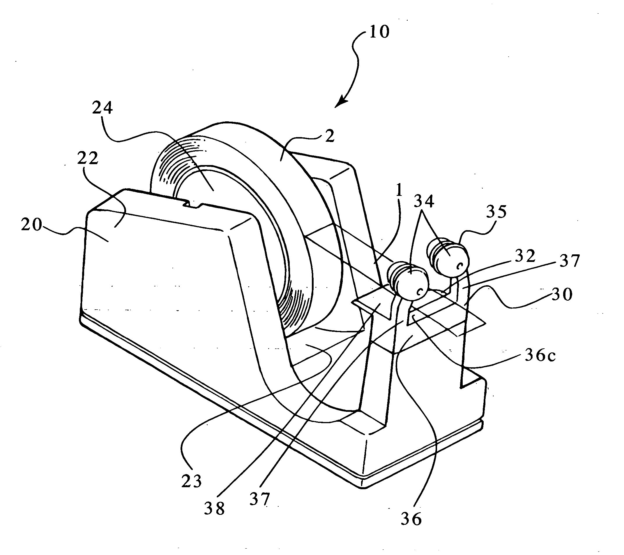
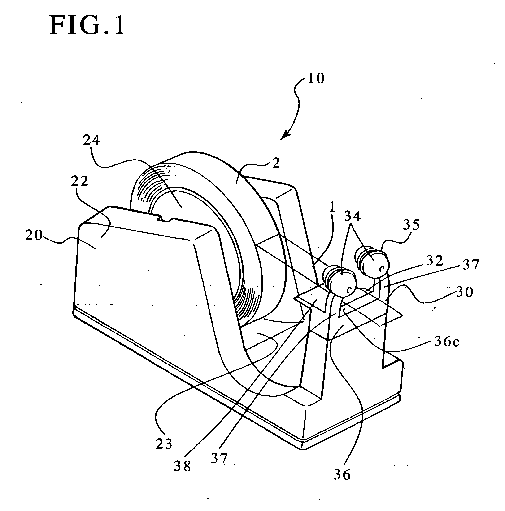
[0026] The adhesive tape cutter according to the present invention will now be explained in detail based on an embodiment illustrated in the drawings. FIG. 1 is a perspective view of an adhesive tape cutter according to the present invention. FIG. 2 is a side view of the adhesive tape cutter. FIG. 3 is a front view of the adhesive tape cutter. FIG. 4 is a front view of the cutting mechanism. FIG. 5 is a cross section of the cutting mechanism along A-A. FIG. 6 is an exploded perspective view of the cutter.

[0027] The adhesive tape cutter 10 according to the present invention consists of a holding mechanism 20, cutting mechanism 30 and cutting mechanism support member 36.

[0028] The holding mechanism 20 consists of a tape cutter proper 22, reel 24 and mounting hole 26. The tape cutter proper 22 is the cutter body that combines the functions of containing and cutting adhesive tape in the shape of a long, thin rectangular parallelepiped, with an indentation 23 for containing tape formed...


PUM

PropertyMeasurementUnit
Angleaaaaaaaaaa
Angleaaaaaaaaaa
Diameteraaaaaaaaaa

Abstract

An adhesive tape cutter is provided with a circular cutting blade, and by making the cutting portion that comes into contact with the tape a roughly 90° partial arc, cutting is possible in the center and also even if the tape is twisted to either the left or right, a cut can be easily made and the tape can be easily cut. The adhesive tape cutter consists of a tape holding mechanism, cutting mechanism, and a support member. The cutting mechanism consists of a circular cutting blade disposed perpendicular to the lengthwise direction of adhesive tape unwound from the roll, and a left and right pair of rotating protective members above the circular cutting blade that also serve as tape guides and that rotate in a direction perpendicular to the lengthwise direction of the tape. The protective members have a structure wherein the bottom surfaces of two hemispheres of different diameters face each other and the flange portion of the bottom edges are linked while separated by a fixed gap, and are also disposed above said circular cutting blade at a distance such that the fingertip does not reach the cutting blade when adhesive tape is pushed down by hand and cut.

Description

BACKGROUND OF THE INVENTION [0001] 1. Field of the Invention [0002] The present invention relates to an adhesive tape cutter used for unrolling adhesive tape that is wound into a roll and cutting it to the desired length, and particularly to an improved adhesive tape cutter that uses circular cutting blades as the cutting blades and can thus withstand long-term usage. [0003] 2. Description of Related Art [0004] An adhesive tape cutter typically comprises a tape cutter body that rotatably holds adhesive tape rolled into a roll shape and a saw tooth-shaped cutting blade for cutting the adhesive tape, in a configuration whereby adhesive tape unrolled from the roll is cut to the desired length with the cutting blade. Conventional adhesive tape cutters use saw tooth-shaped cutting blades that are serrated and so do not cut well, and also the cut edge of the tape is also serrated in shape, and thus they have drawbacks in that when tape is applied to the desired area, the clean appearance ...

Claims


Application Information

Patent Timeline
IPC IPC(8): B65H35/07B65H35/00
CPCB65H35/0026Y10T156/1348Y10T156/1322B65H35/0086Y10T83/7734Y10T225/238Y10T225/247
Inventor NAKAYAMA, MASAYUKI
Owner KTF
Why Eureka
Try Eureka