
Test system for evaluating feedback performance of a listening device

a listening device and feedback technology, applied in the field of acoustic feedback, can solve problems such as higher-than-realistic throughput delay

Inactive Publication Date: 2015-12-01
BERNAFON
View PDF18 Cites 1 Cited by
  • Summary
  • Abstract
  • Description
  • Claims
  • Application Information

AI Technical Summary

Benefits of technology

[0023]This has the advantage of allowing a determination of frequencies where a particular listening device is prone to acoustic feedback.
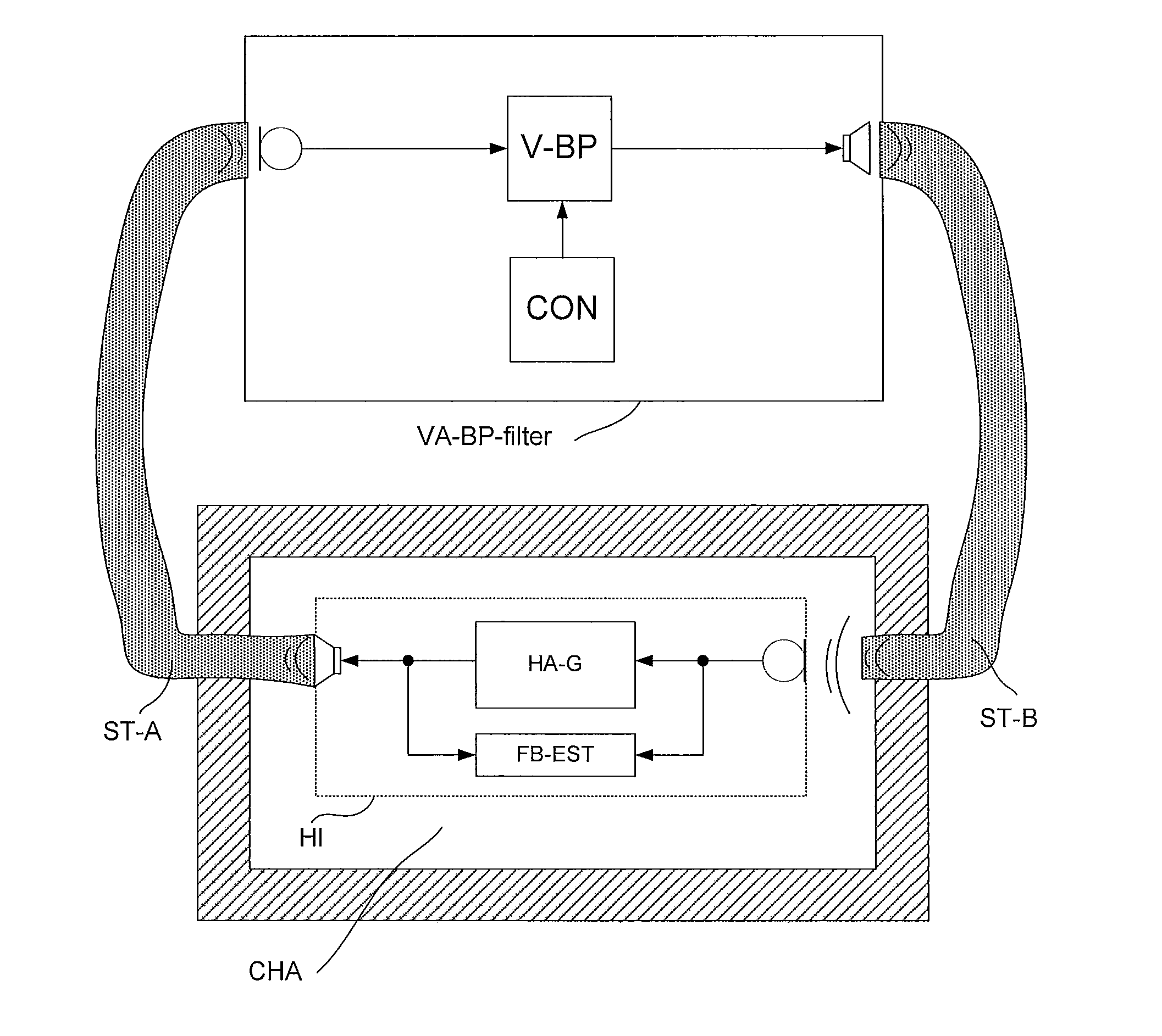
[0026]In an embodiment, the variable filter is a variable acoustic filter. In an embodiment, the variable filter comprises an enclosure comprising a cavity with a variable volume allowing an acoustic resonance frequency of the system to be varied. In an embodiment, the enclosure comprising a cavity with a variable volume comprises a body comprising cylindrical or prismatic inner walls and two transversal walls. In an embodiment, the transversal walls comprise a bottom wall and a piston being adapted for sliding along the cylindrical or prismatic inner walls, whereby the volume of the cavity between the piston and the bottom wall can be varied. In an embodiment, both transversal walls of the cavity are movable. In an embodiment, the control unit for changing a transfer function of the filter is adapted for controlling the volume of the cavity. In an embodiment, the control unit for changing a transfer function of the filter comprises a piston (and possibly an element for controlling its movement). In an embodiment, the enclosure comprises a flexible material allowing its volume to be modified (over an appropriate range, e.g. adapted to the application in question). The use of a variable (all) acoustic filter has the advantage of minimizing delay in the feedback path of the test system.
[0031]This has the advantage that the variable filter can be controlled by electric means. In an embodiment, the variable filter comprises a (electric) control unit for controlling the filtering properties of the variable electric filter. In an embodiment, the variable electric filter is adapted to compensate for unintended filtering introduced by other parts of the test system, e.g. the propagation elements and / or a possible chamber enclosing the listening device. In an embodiment, the variable electric filter is a programmable filter bank. In an embodiment, the variable electric filter comprises a band-pass filter whose centre frequency (and possibly band width) is selectable (and / or variable). In an embodiment, the variable electric filter comprises a FIR filter or an IIR filter. In an embodiment, the control unit for changing a transfer function of the variable filter is adapted to control filter coefficients of the variable electric filter. In an embodiment, the control unit is adapted to introduce a delay in the signal path of the variable filter.
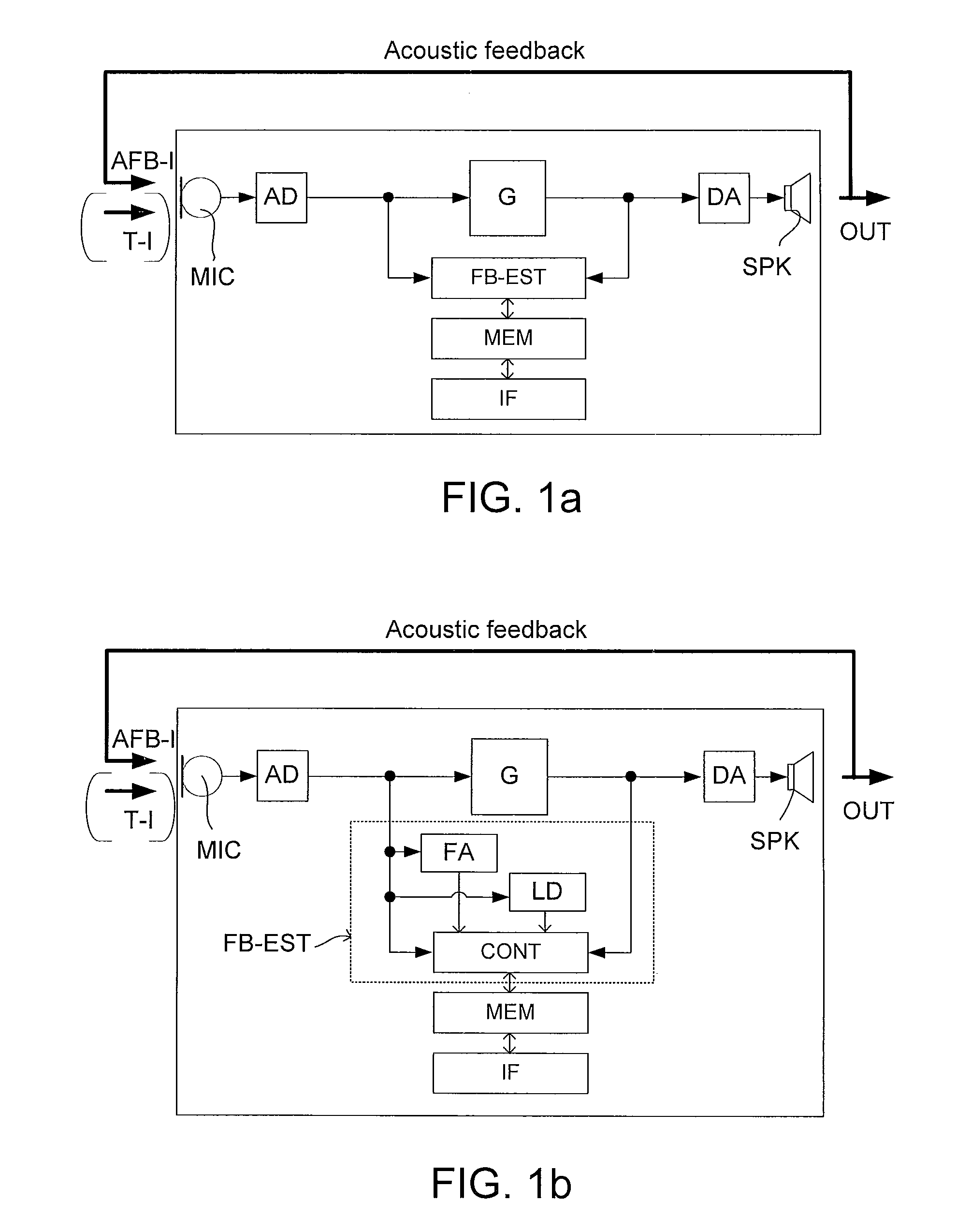
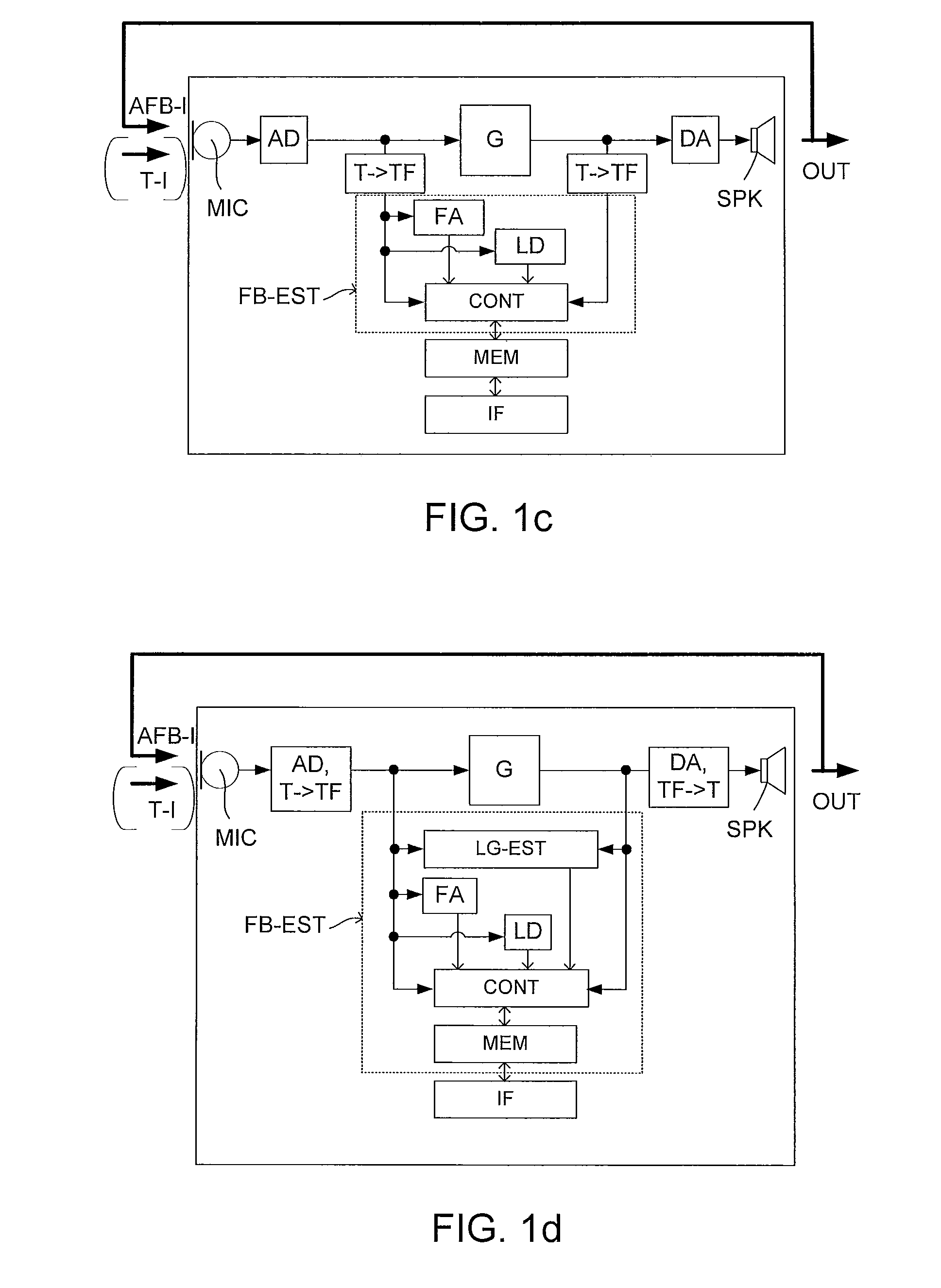
[0035]In an embodiment, the analysing unit comprises a communication interface to the listening device allowing exchange of data and commands. The listening device may comprise a feedback estimation unit for estimating current feedback in the listening device (preferably at a number of frequencies), such current feedback values being made available to the test system via said communication interface. The listening device preferably comprises a memory for storing estimated feedback values (e.g. at different points in time). In an embodiment, the memory form part of a data logger for logging various operational parameters, e.g. including the occurrence of acoustic feedback, of the listening device, over time. In an embodiment, the occurrence of acoustic feedback as detected by the listening device is logged over time and frequency. The detected feedback values in the listening device can be transferred to the analysing unit via the communication interface for further processing and analysis. Alternatively or additionally, the analysing unit may be adapted to estimate feedback in the listening device, while connected to the listening device via the communication interface. Thereby the analysing unit is able to change the transfer function of the variable filter in harmony with the detection of feedback in the listening device. Further, it allows a procedure where the variation of the transfer function of the variable filter and the corresponding feedback measurement are performed (e.g. automatically performed) according to a predefined scheme. In an embodiment, the analysing unit is adapted to run a fitting software for controlling data and processing parameters of the listening device and for reading data (e.g. stored feedback values) from the listening device. This has the advantage that the listening device and the test measurement can be controlled from the (same) analysing unit, whereby parameters (e.g. a gain, e.g. a gain in a particular frequency band) of the listening device can be easily changed prior to initiation of a feedback measurement, possibly in an automated procedure.
[0039]In an embodiment, the test system comprises a chamber for enclosing parts of or the whole of one or more of the listening device, the variable filter and the propagation elements. This has the advantage that important parts of the test system can be acoustically isolated from acoustic signals from the environment.

Problems solved by technology

However, since throughput delay plays an important role in feedback cancellation, such systems are often not satisfactory, because they have a higher-than-realistic throughput delay.

Method used


Image

  • Test system for evaluating feedback performance of a listening device
  • Test system for evaluating feedback performance of a listening device
  • Test system for evaluating feedback performance of a listening device

Examples


example

[0131]An example of a feedback verification procedure is outlined in the following. In an embodiment, the listening device, e.g. in the form of a hearing instrument, comprises a “tone detector” configured to detect whether or not the signal contains feedback (optionally to detect a level of feedback) at a particular frequency. The results of feedback detection measurements performed at different frequencies (and possibly averaged over time) are logged in a memory of the listening device (or in a memory coupled to the listening device via an interface, cf. IF in FIG. 1). In an embodiment, the memory is implemented as data logger of the listening device. If the tone detector detects “feedback”, then the data logger increases one counter in an indexed array of counters. The array index is e.g. chosen based on the estimated feedback frequency. At fitting time, where a PC running fitting software for customizing software of the hearing instrument is connected with the hearing instrument ...


PUM


Abstract

A test system for evaluates acoustic feedback characteristics of a listening device by changing the transfer function of the signal path from an acoustic output to an acoustic input of the listening device. A variable filter comprises an acoustic input, an acoustic output, and a control unit for changing a transfer function of the filter. First and / or second acoustic propagation elements propagate acoustic sound, the first acoustic propagation element acoustically connecting the acoustic output of the listening device with the acoustic input of the variable filter, the second acoustic propagation element acoustically connecting the acoustic output of the variable filter with the acoustic input of the listening device; wherein the system is configured to allow a determination of acoustic feedback or a level of acoustic feedback of the listening device at different frequencies.

Description

[0001]This nonprovisional application claims the benefit of U.S. Provisional Application No. 61 / 483,764 filed on May 9, 2011 and to patent application Ser. No. 11 / 165,225.1 filed in Europe on May 9, 2011. The entire contents of all of the above applications is hereby incorporated by reference.TECHNICAL FIELD[0002]The present application relates to acoustic feedback, in particular to the verification of acoustic feedback in listening devices, e.g. hearing aids. The disclosure relates specifically to a test system for evaluating acoustic feedback characteristics of a listening device by systematically changing the transfer function of the signal path from an acoustic output to an acoustic input of the listening device. The disclosure also relates to use of the test system. The disclosure further relates to a combination of a test system and a listening device.[0003]The application furthermore relates to a method of characterizing acoustic feedback at different frequencies from an acou...

Claims


Application Information

Patent Timeline
Patent Type & Authority Patents(United States)
IPC IPC(8): H04R29/00G10K11/04H03H9/38H04R25/00G10K11/00G10K11/22
CPCH04R25/30G10K11/004G10K11/04H03H9/38H04R25/70G10K11/22H04R25/453
Inventor LAMM, JESKOTRACHSEL, THOMASBUETIKOFER, JANIKMOSER, HANS-JURGMORANT, FABIAN
Owner BERNAFON
Learn More