Switch fabric

a technology of ethernet switches and fabric, applied in the field of computer networking, can solve the problems of low cost of switches, network congestion, and shortcoming associated with switches, and achieve the effects of high availability, high capacity, and high capacity

Inactive Publication Date: 2015-12-08
FUNG HEI TAO
View PDF4 Cites 1 Cited by
  • Summary
  • Abstract
  • Description
  • Claims
  • Application Information

AI Technical Summary

Benefits of technology

[0008]It is also an object of the invention that the switch fabric responds quickly to failure and congestion.
[0009]Each switch in the highest tier stores a plurality of alternate paths for a packet destined to an external device. The switch sends out probing packets to test viability of the alternate paths and avoids the broken paths.
[0010]The invention addresses the typical requirements of a typical data center network, namely scalability, high-availability, and efficiency. The system is scalable because more switches may be added to provide higher capacity and expand the switch fabric in number of tiers and in numbers of switches in tiers. The system is highly-available because there can be built-in redundancy in connectivity and capacity and a failure in a switch port or a switch can be alleviated by responding quickly in leveraging the redundancy. The system is efficient because of its ability in load-balancing the traffic taking advantage of the redundancy.

Problems solved by technology

However, there are short-comings associated with that.
For example, the switching paths among end-stations are static, and the network therefore is susceptible to network congestion without alleviation.
Those switches are relatively low-cost, but they also have severe limitations in terms of the number of classification entries and the variety of classification keys.
The severe limitations of those switches greatly discount the ability because the number of flows that can be configured on those switches is relatively small, e.g. in thousands.
However, the assumption that the control plan can configure many (e.g. millions) of flows via OpenFlow or even any other communications protocol functionally similar to OpenFlow to the data plane may not hold.

Method used


Image

  • Switch fabric
  • Switch fabric
  • Switch fabric

Examples


Embodiment Construction

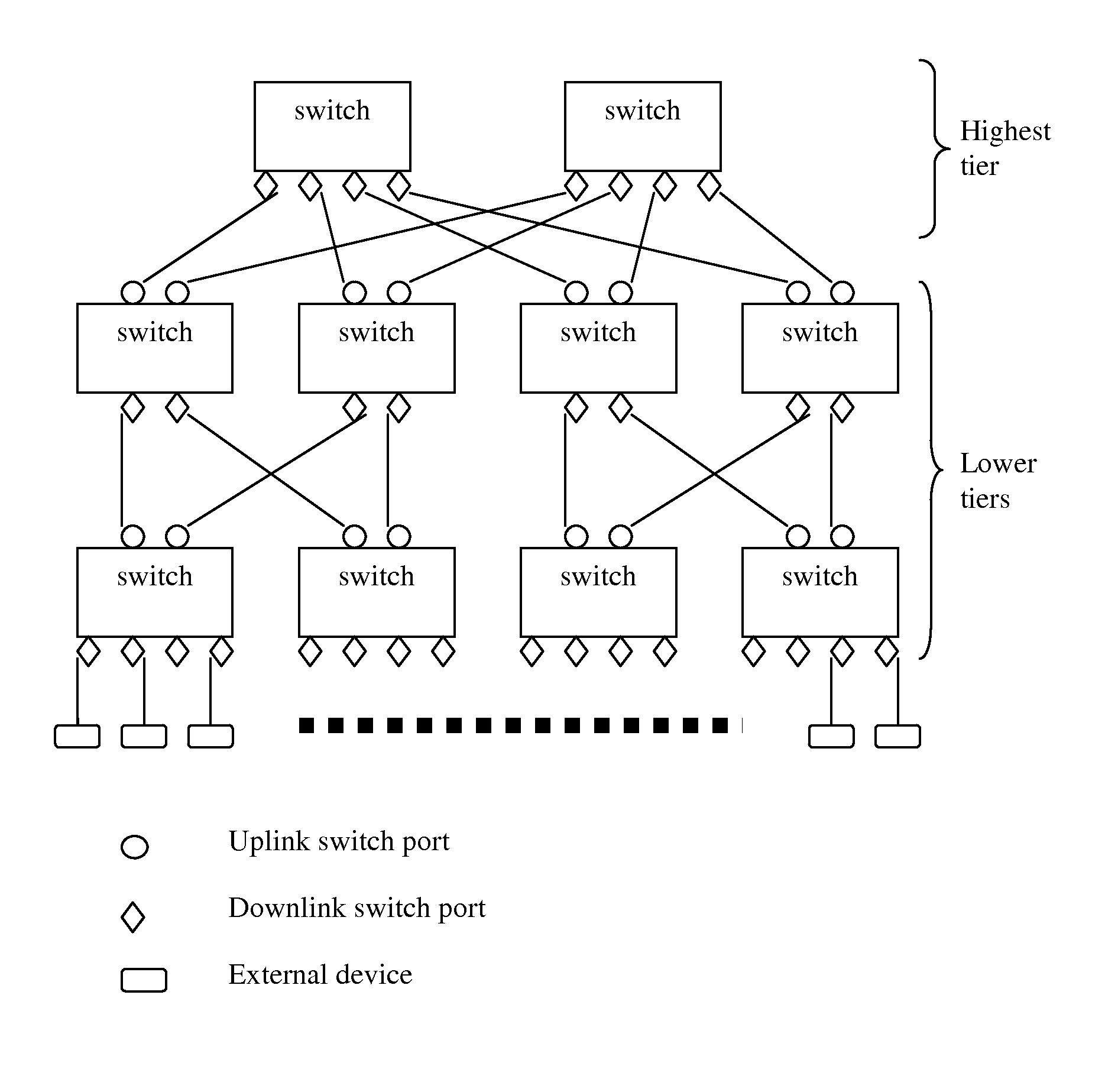
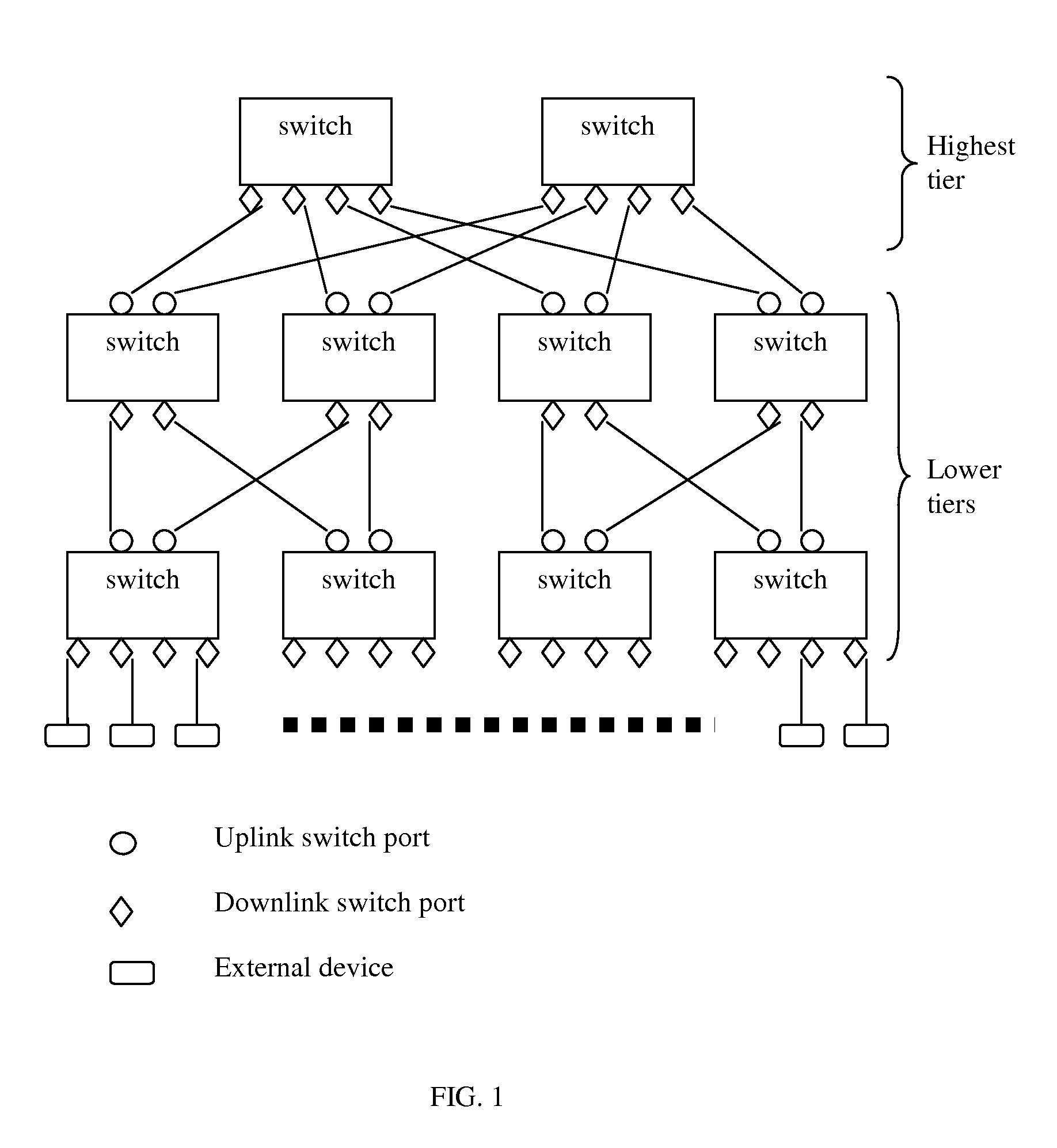
[0023]The system comprises a plurality of switches organized in tiers. There should be at least one tier. To scale the system, however, there should be multiple tiers. A switch has a limited number of switch ports. In other words, there are a limited number of connections that can be made to a switch. To support many external devices connected to the system, the system should have many switches. The switches should be interconnected to provide communications among the external devices. Organizing the switches in tiers would achieve inter-connectivity. Packets from an external device may enter a switch in the lowest tier and be forwarded to switches in higher tiers, then eventually to a switch in the highest tier. On the switch in the highest tier, the packets may be subject to typical switching and routing operations. Then the packets are forwarded to switches in the lower tiers, to a switch in the lowest tier, and eventually to the destined external device. Usually, a switch in a h...


PUM


Abstract

A system and methods of using commodity switches to produce a switch fabric are disclosed. The system comprises switches organized in tiers. Each switch is connected to switches in higher tiers via its uplink switch ports and to switches in lower tiers via its downlink switch ports. A packet received from any downlink switch port is forwarded to one of the at least one link aggregation of uplink switch ports. A packet received from any uplink switch port is forwarded according to the first label in the packet. Each switch in the highest tier is configured to insert one or more labels in a packet to be sent out via the switches. A value in a label indicates the switch port to be selected to send out the packet received at a switch.

Description

FIELD OF THE INVENTION[0001]This application related to computer networking and more particularly to building a fabric of Ethernet switches.BACKGROUND[0002]Recently due to the emergence of distributed computing at data centers, a scalable Ethernet switch network that has congestion alleviation capability becomes desirable. Connecting Ethernet switches in a fat-tree topology and managing them as a typical Local Area Networks (LANs) with spanning tree protocol (STP) or as a typical Internet Protocol (IP) subnets with routing protocols has been known to allow an Ethernet switch network to grow in scale. However, there are short-comings associated with that. For example, the switching paths among end-stations are static, and the network therefore is susceptible to network congestion without alleviation.[0003]Software defined networking (SDN) is an approach to building a computer network that separates and abstracts elements of the networking systems. It has become more important with th...

Claims


Application Information

Patent Timeline
Patent Type & Authority Patents(United States)
IPC IPC(8): H04L12/933H04L12/931H04L12/947H04L12/709H04L45/243
CPCH04L49/1515H04L49/351H04L49/50H04L45/245
Inventor FUNG, HEI TAO
Owner FUNG HEI TAO
Why Eureka
Try Eureka