Unlock instant, AI-driven research and patent intelligence for your innovation.

Liquid ejecting apparatus

a technology of liquid ejecting apparatus and ejector, which is applied in the direction of printing, other printing apparatus, etc., can solve the problems of difficult electrical charging foreign matter that is not easily drawn or attracted to the front surface and the difficulty of electrical charging or other problems of the light-transmitting member

Active Publication Date: 2015-12-15
SEIKO EPSON CORP
View PDF7 Cites 0 Cited by
  • Summary
  • Abstract
  • Description
  • Claims
  • Application Information

AI Technical Summary

Benefits of technology

This patent describes a liquid ejecting apparatus that can prevent the imaging accuracy of the medium from declining. The apparatus includes a conductive member that is mounted on or connected to the medium supporting unit, which prevents charging of the irradiation region and improves the imaging accuracy of the medium. The front surface of the light-transmitting member, which is facing the medium, can be selected by the manufacturer when installing the light-transmitting member on the medium supporting unit, increasing work efficiency. Additionally, the apparatus includes a suction hole for easily removing foreign matter from the front surface of the light-transmitting member.

Problems solved by technology

In one example, because the antistatic film is formed on the front surface of the light-transmitting member, it is difficult for the light-transmitting member to be or to become electrically charged.
Therefore, foreign matter such as paper powder and dust are not easily drawn or attracted to the front surface of the light-transmitting member by electrostatic induction.
As a result, the foreign matter is not easily attached to the front surface of the light-transmitting member.

Method used


Image

  • Liquid ejecting apparatus
  • Liquid ejecting apparatus
  • Liquid ejecting apparatus

Examples


Embodiment Construction

[0027]Hereinafter, an ink jet type printer, which is an embodiment of a liquid ejecting apparatus, will be described with reference to drawings.

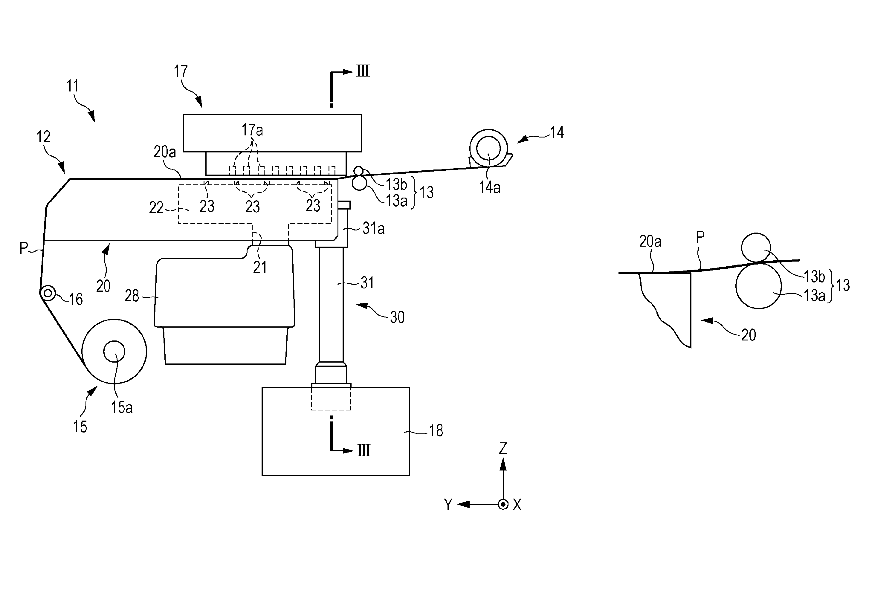
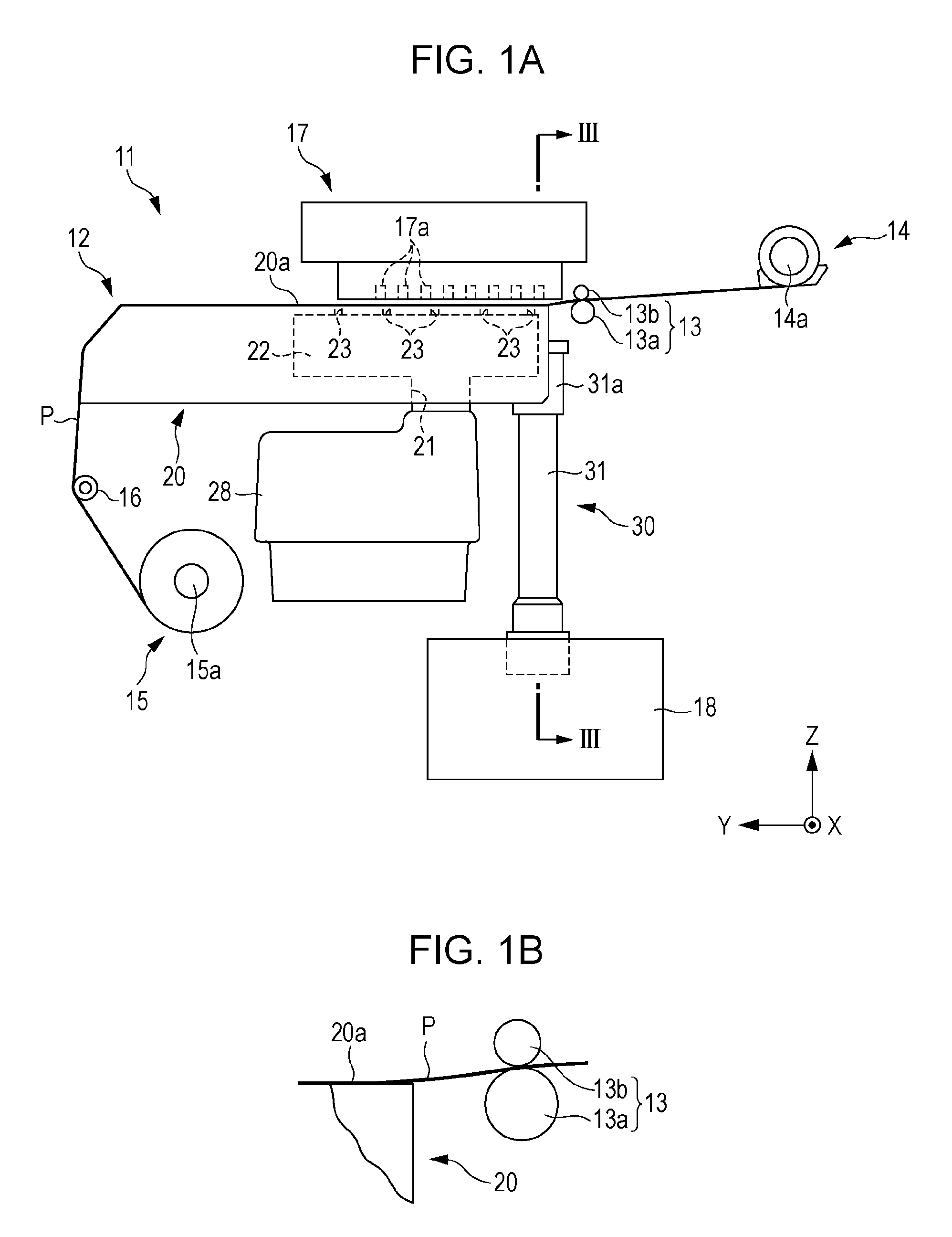
[0028]FIG. 1A illustrates an ink jet type printer, which is an example of a liquid ejecting apparatus. As illustrated in FIG. 1A, the ink jet type printer (hereinafter, referred to as a “printer 11”) includes a transportation device 12 that transports a long sheet-shape continuous form paper P, which is an example of a medium. The printer 11 includes an ejecting unit 17 that performs printing by ejecting ink onto the continuous form paper P being transported by the transportation device 12. In addition, the printer 11 includes a control unit 18 that controls the transportation device 12 and the ejecting unit 17.

[0029]The transportation device 12 includes a feeding portion 14 feeding the continuous form paper P, and a winding portion 15 winding the continuous form paper P which is fed from the feeding portion 14 and is printed using the eject...


PUM


Abstract

A printer includes a transportation unit that transports a continuous form paper, an ejecting unit that ejects ink onto the continuous form paper, a continuous form paper supporting unit that includes a supporting surface capable of supporting the continuous form paper so as to be opposite to the ejecting unit, a light-transmitting glass that is mounted at a position in the medium supporting unit which faces the continuous form paper transported by the transportation unit, an imaging unit that captures an image of the continuous form paper which passes over a front surface of the light-transmitting glass, a control unit that controls a transportation amount of the continuous form paper based on the image captured by the imaging unit, and a suction fan that generates an airflow onto the front surface of the light-transmitting glass. An antistatic film is formed on the front surface of the light-transmitting glass.

Description

CROSS-REFERENCE TO RELATED APPLICATIONS[0001]The present application claims priority to Japanese Patent Application No. 2014-066992 filed on Mar. 27, 2014, which is hereby incorporated by reference in its entirety.BACKGROUND[0002]1. Technical Field[0003]Embodiments of the present invention relate to a liquid ejecting apparatus including an imaging unit.[0004]2. Related Art[0005]As a liquid ejecting apparatus ejecting liquid such as ink from an ejecting unit onto a medium such as paper, a liquid ejecting apparatus, in which a medium supporting unit supporting a medium is provided with an imaging unit, a texture on a rear surface of the medium that passes over the medium supporting member is imaged by the imaging unit, and a transportation amount of a medium is detected on the basis of the imaged image, has been known. In the liquid ejecting apparatus, an opening portion for irradiating a rear surface of the medium with light from the imaging unit is provided on a supporting surface o...

Claims


Application Information

Patent Timeline
Patent Type & Authority Patents(United States)
IPC IPC(8): B41J29/393B41J11/00B41J11/42B41J13/00B41J15/00B41J15/04
CPCB41J11/0085B41J11/42B41J13/0027B41J15/00B41J15/048B41J11/0095B41J29/17
Inventor IDE, MITSUTAKAMUROTANI, TOMOYAKOBAYASHI, HIROYUKI
Owner SEIKO EPSON CORP
Features
  • R&D
  • Intellectual Property
  • Life Sciences
  • Materials
  • Tech Scout
  • Unparalleled Data Quality
  • Higher Quality Content
  • 60% Fewer Hallucinations
Learn More