Wall formed in soil, the wall including a hollow prefabricated element, and a method of making such a wall

a prefabricated element and wall technology, applied in the field of special works in soil, can solve the problems of long transportation of prefabricated elements from the fabrication workshop to the site, long transportation of prefabricated elements, and inability to meet the needs of the soil, and achieve the effect of facilitating self-hardening materials

Active Publication Date: 2015-12-15
SOLETANCHE FREYSSINET SAS
View PDF18 Cites 16 Cited by
  • Summary
  • Abstract
  • Description
  • Claims
  • Application Information

AI Technical Summary

Benefits of technology

[0007]An object of the present invention is to provide a wall presenting all of the advantages of a conventional prefabricated wall, but also making it possible to lower costs and to limit the constraints associated with transport and with fabricating prefabricated elements.

Problems solved by technology

Nevertheless, that technique presents drawbacks associated with the prefabricated elements that are used.
Furthermore, transporting the elements from the fabrication workshop to the site is lengthy and expensive because of their great weight.

Method used


Image

  • Wall formed in soil, the wall including a hollow prefabricated element, and a method of making such a wall
  • Wall formed in soil, the wall including a hollow prefabricated element, and a method of making such a wall
  • Wall formed in soil, the wall including a hollow prefabricated element, and a method of making such a wall

Examples


Embodiment Construction

[0052]The prefabricated walls are made conventionally out of individual panels, either in succession or in alternation.

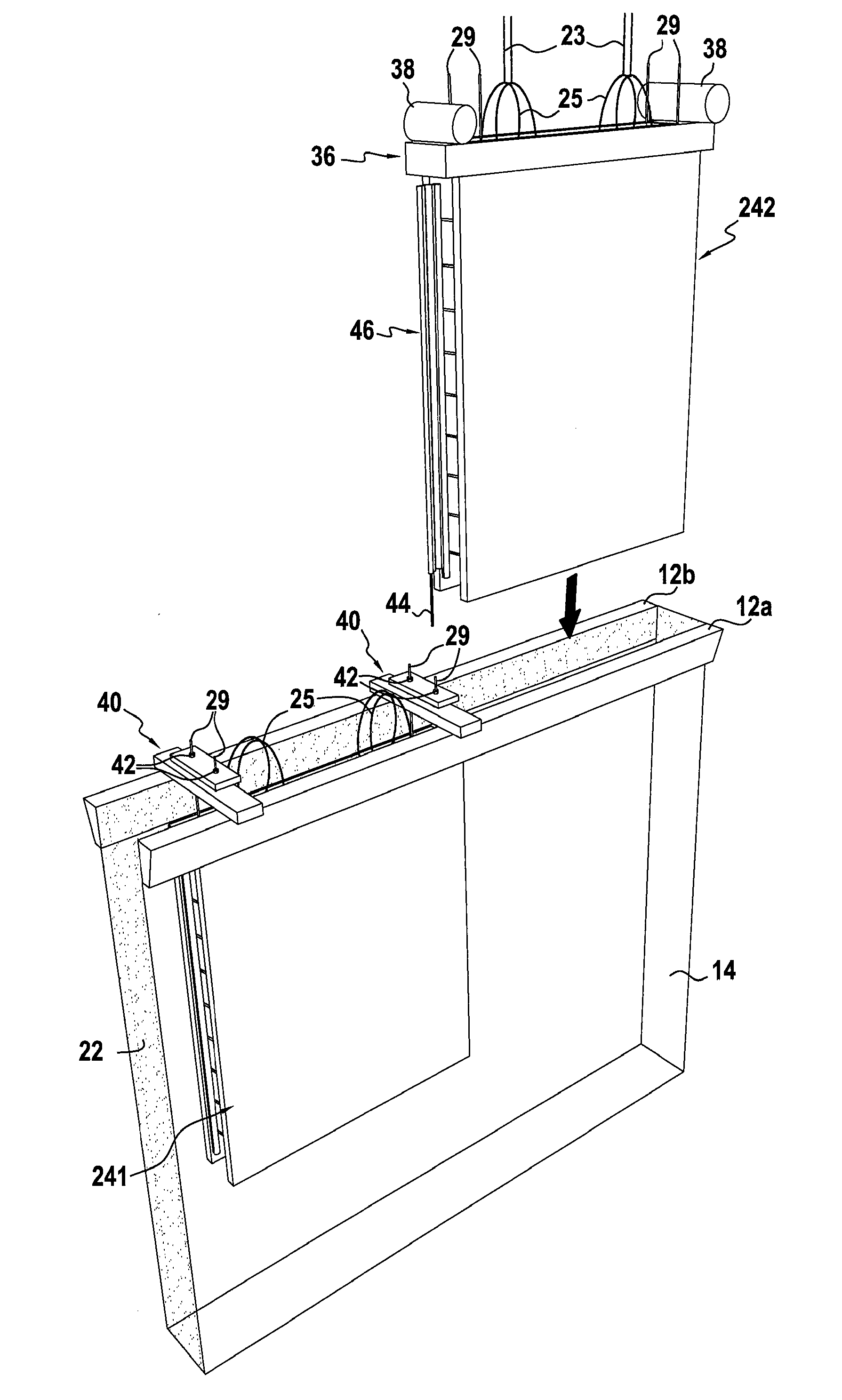
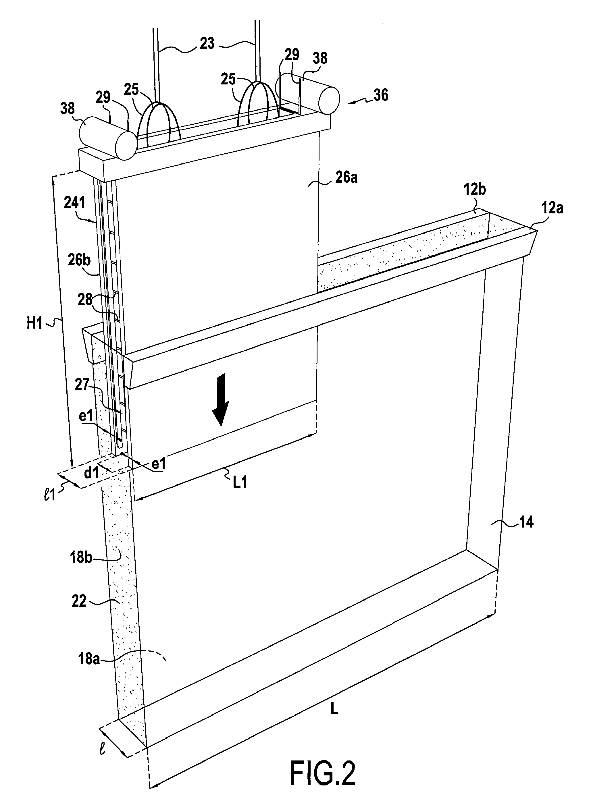
[0053]With reference to FIGS. 1 to 9, there follows a description of how a wall 10 of the invention is made using successive panels. All of the techniques described are naturally applicable to make a wall using alternating panels, or indeed making a wall that is constituted by a single individual panel.

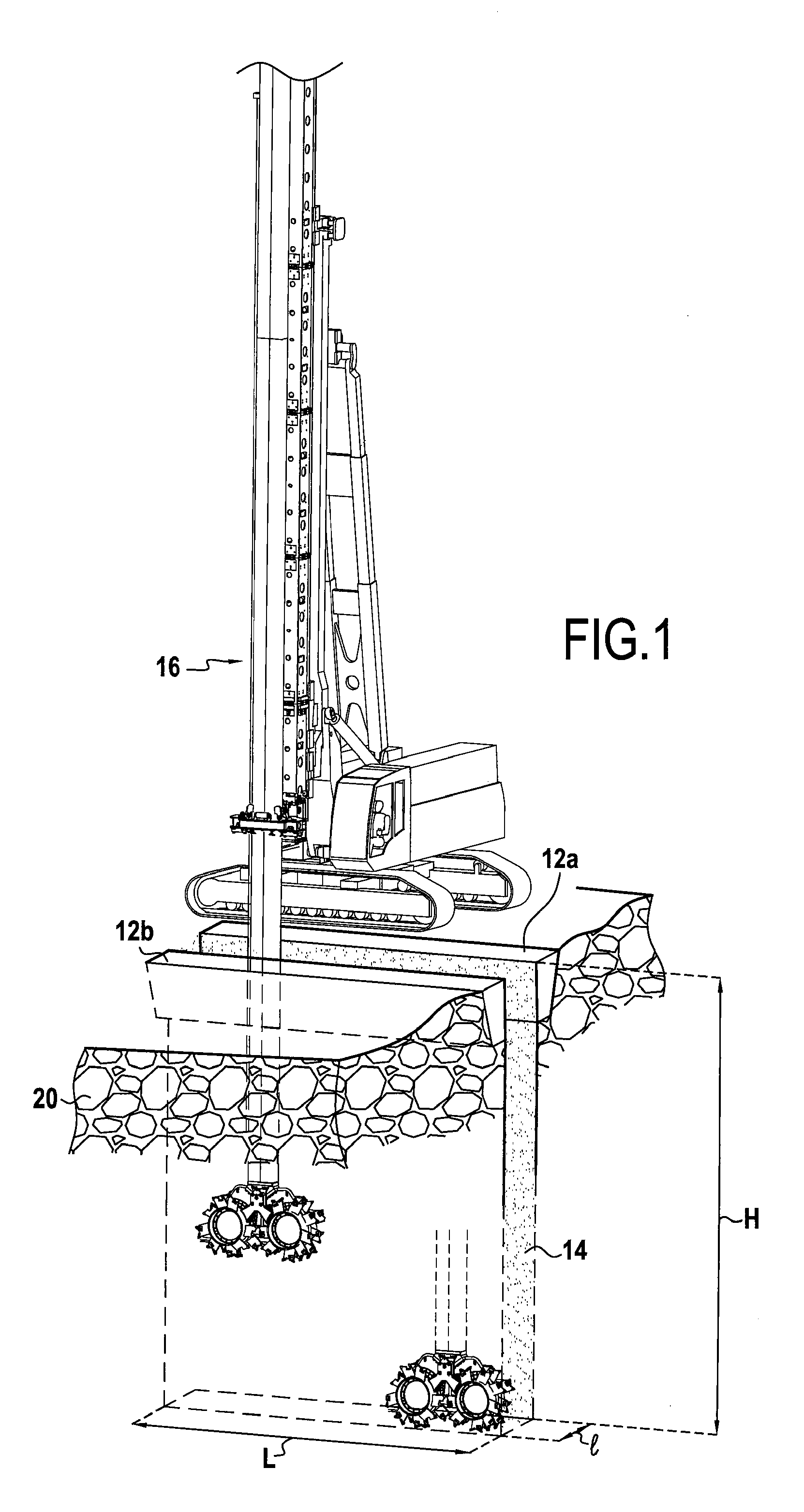
[0054]A first step of the method, shown in FIG. 1, consists in making low guide walls 12a, 12b serving to mark the location of the future wall 10. In the example, two mutually parallel low guide walls 12a and 12b define a space of constant width l corresponding substantially to the width desired for the future wall. These low guide walls 12a, 12b are generally made of reinforced concrete and they present a height lying in the range about 0.5 meters (m) to about 1.50 m. Their function is to ensure stability of surface ground, constituting leveling markers, and serving ...


PUM


Abstract

A method for making a wall in soil. The method may include forming a trench in the soil; filling the trench with a self-hardening material; supplying at least one prefabricated element that has two plates connected together by a connection member; and positioning the prefabricated element in the trench filled with the self-hardening material.

Description

FIELD OF THE INVENTION[0001]The present invention relates to the field of special works in the soil.[0002]It relates more particularly to a wall formed in the soil, together with a method of making such a wall.BACKGROUND OF THE INVENTION[0003]Conventional diaphragm walls are known in which concrete is cast directly into a trench formed in the soil and after a cage of metal bars has been put into place.[0004]Since the beginning of the 1970s, as an alternative solution to diaphragm walls, prefabricated walls have been used in which reinforced concrete elements, prefabricated either on site or in a workshop, are lowered into an excavated trench, which is then filled with a slurry of cement-bentonite for sealing the prefabricated elements to the ground in place.[0005]The prefabricated wall technique is preferred in particular when the wall is incorporated in the final work and needs to satisfy aesthetic criteria, or when the thickness of the wall needs to be optimized, or when there are...

Claims


Application Information

Patent Timeline
Patent Type & Authority Patents(United States)
IPC IPC(8): E02D29/05E02D5/18E02D17/13
CPCE02D5/18E02D17/13
Inventor BOREL, SERGEHAMELIN, JEAN PIERRECANO, JOELMATHIEU, FABRICE
Owner SOLETANCHE FREYSSINET SAS
Why Eureka
Try Eureka