Communication terminal, base station, wireless communication system, control method and program therefor, and recording medium having control program recorded thereon

a communication terminal and control method technology, applied in the field of communication terminals, base stations, wireless communication systems, control methods and programs therefor, and recording mediums having control programs recorded thereon, can solve the problems of global difficulty in lte-a communication system wide continuous frequency bands, and achieve the effect of preventing deterioration in communication control accuracy, ensuring accuracy, and ensuring accuracy

Active Publication Date: 2015-12-15
SHARP KK
View PDF10 Cites 0 Cited by
  • Summary
  • Abstract
  • Description
  • Claims
  • Application Information

AI Technical Summary

Benefits of technology

[0035]As described above, in the wireless communication system of the present invention, a communication quality of a non-allocated downlink sub-band that is in the same frequency band as the only-uplink sub-band is measured as a communication quality of a monitor downlink sub-band. Therefore, the communication quality of the only-uplink sub-band can be accessed with accuracy. This makes it possible to control with accuracy uplink transmission in the only-uplink sub-band.
[0036]Further, in the wireless communication system of the present invention, because the base station directly obtains a communication quality of the only-uplink sub-band from a reception power in the only-uplink sub-band which reception power has been measured by the base station. This makes it possible to assess with accuracy the communication quality. As a result, it becomes possible to control with accuracy uplink transmission in the only-uplink sub-band.
[0037]Further, in the wireless communication system of the present invention, a non-allocated downlink sub-band in a frequency band including the only-uplink sub-band is further allocated to the communication terminal. Therefore, the presence of the only-uplink sub-band is eliminated. As a result, it becomes possible to prevent deterioration in accuracy of communication control with respect to the only-uplink sub-band.

Problems solved by technology

However, it is globally difficult to reserve a wide continuous frequency bands for use in the LTE-A communication system.

Method used


Image

  • Communication terminal, base station, wireless communication system, control method and program therefor, and recording medium having control program recorded thereon
  • Communication terminal, base station, wireless communication system, control method and program therefor, and recording medium having control program recorded thereon
  • Communication terminal, base station, wireless communication system, control method and program therefor, and recording medium having control program recorded thereon

Examples


embodiment 1

[0096][Embodiment 1]

[0097]The following discusses an embodiment of the present invention with reference to FIGS. 1 to 18.

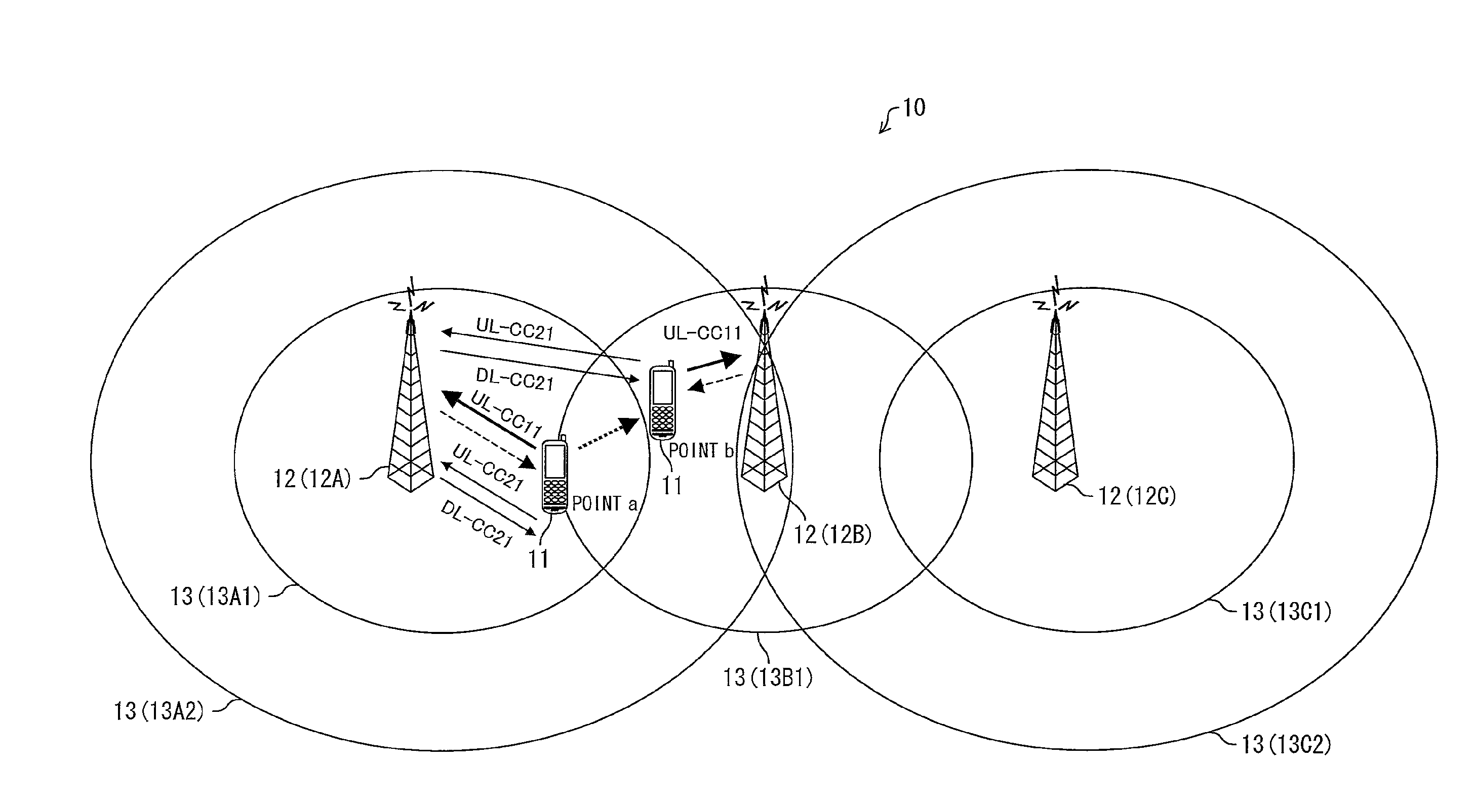
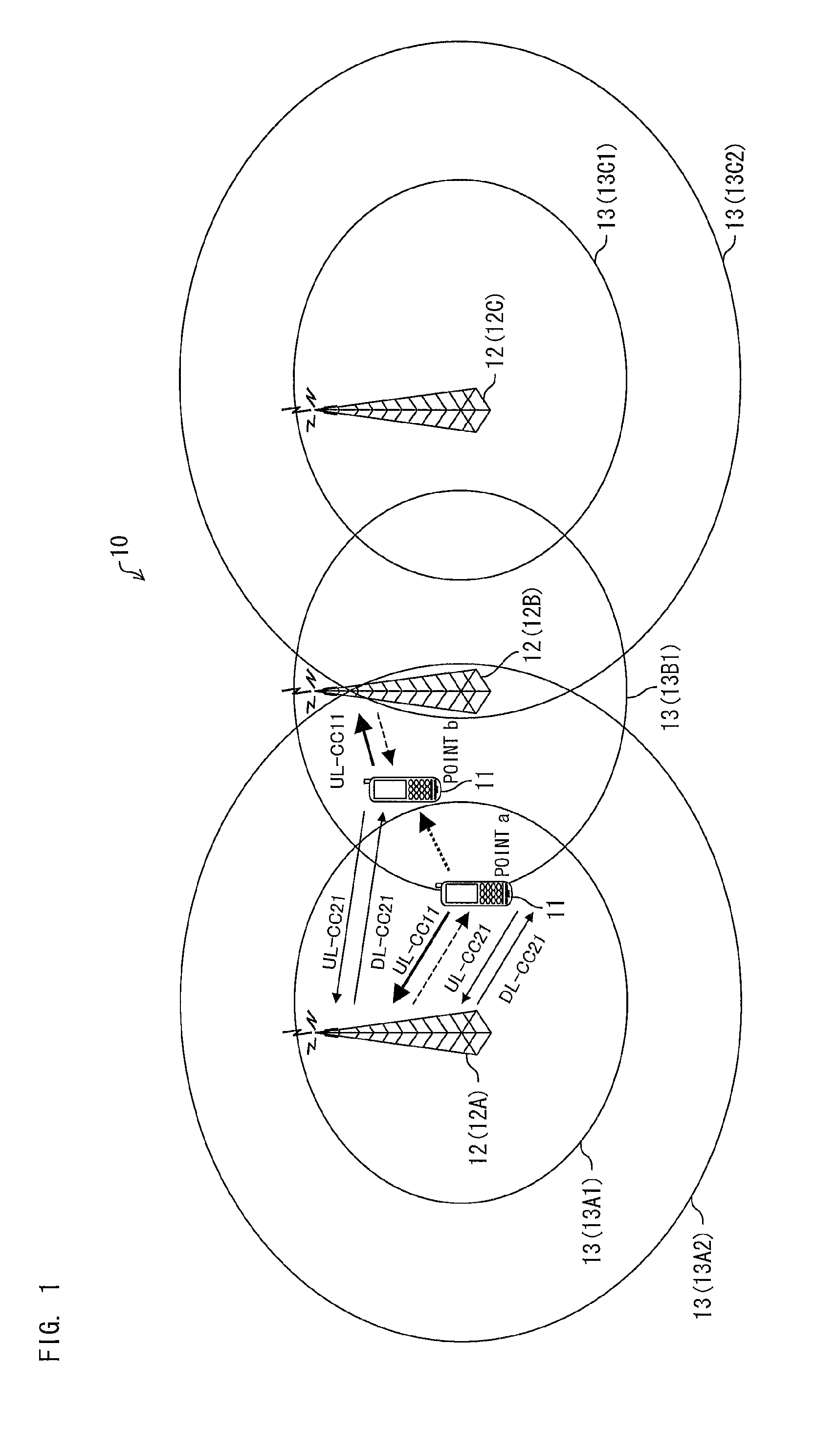
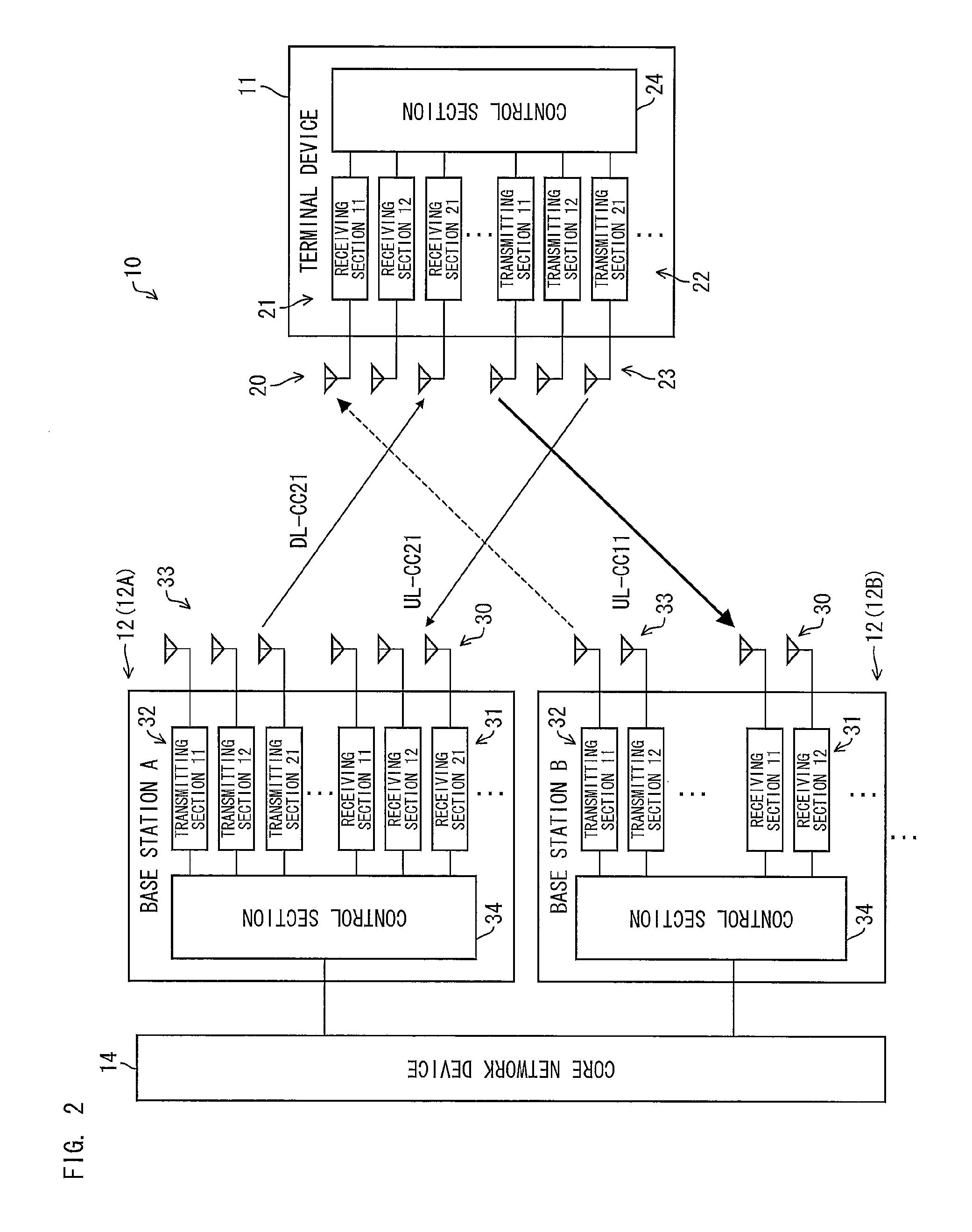
[0098]FIG. 1 is a schematic view of a wireless communication system of Embodiment 1. FIG. 1 illustrates a wireless communication system 10 which includes a wireless communication terminal (hereinafter, abbreviated to a “terminal”) 11 and base stations 12A to 12C each of which communicates wirelessly with the wireless communication terminal 11. Note that, hereinafter, in a case where the base stations 12A to 12C are to be collectively referred to, the term “base station 12” is used.

[0099]In Embodiment 1, two frequency bands (hereinafter, abbreviated to “bands”) FB1 and FB2 are used for the above wireless communication. As illustrated in FIG. 1, the base station 12A uses the bands FB1 and FB2, the base station 12B uses the band FB1 and the base station 12C uses the bands FB1 and FB2.

[0100]FIG. 1 also illustrates (i) a cell 13A1 that is an area where the base station...

embodiment 2

[0201][Embodiment 2]

[0202]Next, another embodiment of the present invention is described below with reference to FIGS. 19 through 26. FIG. 19 is a view schematically illustrating a wireless communication system of the present embodiment.

[0203]According to a wireless communication system 10 shown in FIG. 1, a quality of an onlyUL-CC is managed in such a manner that the terminal 11 (i) monitors a quality of a DL-CC (DL-CC 11) (a broken line arrow in FIG. 1) corresponding to the onlyUL-CC (UL-CC 11) and (ii) notifies the base station 12 of the quality. Meanwhile, according to a wireless communication system 10 shown in FIG. 19, a base station 12 measures and manages a quality of an onlyUL-CC (UL-CC 11). Accordingly, it is unnecessary for a terminal 11 to monitor a quality of a DL-CC (DL-CC 11) corresponding to an onlyUL-CC. Note that members and processes that are similar to those described in Embodiment 1 are given identical reference numerals, and are not explained repeatedly.

[0204]T...

embodiment 3

[0239][Embodiment 3]

[0240]Next, another embodiment of the present invention is described below with reference to FIGS. 27 through 29. FIG. 27 is a view schematically showing a wireless communication system of the present embodiment.

[0241]According to the above embodiments, there exists an onlyUL-CC, and transmission control and the like of the onlyUL-CC are carried out by managing a quality of the onlyUL-CC. Meanwhile, the present embodiment carries out control that allows no onlyUL-CC to exist. For example, in a case where addition of an onlyUL-CC is desired, control that adds not only the UL-CC but also a DL-CC corresponding to the UL-CC is always carried out. Note that members and processes that are similar to those of the above embodiments are given identical reference numerals, and are not explained repeatedly.

[0242]FIG. 27 shows a state that is shifted from the state shown in (a) of FIG. 17 and in which state one of the two UL-CCs currently under communication in the band FB2 ...


PUM


Abstract

According to a control method of a wireless communication system in which wireless communication between a base station (12) and a communication terminal (11) is carried out by use of a plurality of discontinuous frequency bands, in a case where an onlyUL-CC having no existing corresponding DL-CC is present (S21), a communication quality of a DL-CC in a frequency band including the onlyUL-CC is measured as a communication quality of a DL-CC corresponding to the onlyUL-CC (S22) for the purpose of accurate control of the onlyUL-CC.

Description

CROSS REFERENCE TO RELATED APPLICATIONS[0001]This application is the National Phase of PCT / JP2011 / 077983 filed on Dec. 2, 2011, which claims priority under 35 U.S.C. 119(a) to Application No. 2010-270605 filed in Japan on Dec. 3, 2010, all of which are hereby expressly incorporated by reference into the present application.TECHNICAL FIELD[0002]The present invention relates to (i) a wireless communication system in which wireless communication between a communication terminal and a base station is carried out by use of a plurality of frequency bands, (ii) the communication terminal and the base station of the wireless communication system, (iii) a control method and a control program each for the wireless communication system, the communication terminal, and the base station, and (iv) a storage medium in which the central program is stored.BACKGROUND ART[0003]3GPP (3rd Generation Partnership Project) is currently formulating specifications for an LTE (Long Term Evolution) communicati...

Claims


Application Information

Patent Timeline
Patent Type & Authority Patents(United States)
IPC IPC(8): H04L29/06H04L12/701H04W72/04H04L5/00H04W24/10H04W72/08
CPCH04W72/0406H04L5/001H04L5/006H04L5/0091H04W24/10H04W72/085H04L5/0023H04W72/542H04W72/20
Inventor ISHIKURA, KATSUTOSHITSUNEKAWA, KOICHIOHSIMA, AKIRAKAMENO, TOSHIAKIKONNO, YOSHIO
Owner SHARP KK
Why Eureka
Try Eureka