
Two dimensional barcode and method of authentication of such barcode

a two-dimensional barcode and authentication method technology, applied in the field of two-dimensional barcode and authentication method of such barcode, can solve the problems of easy copying or imitation, inconvenient verification, and inability to integrate or integrate production processes using all such methods, and achieve the effect of improving the security level of authentication of 2d barcod

Active Publication Date: 2017-03-14
SCANTRUST
View PDF44 Cites 21 Cited by
  • Summary
  • Abstract
  • Description
  • Claims
  • Application Information

AI Technical Summary

Benefits of technology

The patent describes a method for improving the security of barcodes by using a primary information portion and a separate secondary information portion. The secondary information is physically separated from the primary information and is designed to be easily detected and copied. The secondary information is formed by a visible separated pattern that is different from the pattern used in other barcodes, making it harder to copy. The secondary information is also designed to have a high information density, which reduces the likelihood of geometrical distortions or aberrations during reproduction. The method also allows for a signature to be added to the barcode for added security. Overall, this method improves the security of barcodes and makes them more difficult to counterfeit or copy.

Problems solved by technology

However, all such methods are known to be either expensive or inconvenient to integrate in production processes.
In addition, they are inconvenient to verify, and easy to copy or imitate.
Notably, a Digital Authentication Code (DAC) that gets degraded such that the degradation has a certain error rate contained within pre-determined boundaries.
However, this may affect its readability.
Furthermore, the DAC itself can be difficult to read as it covers a large surface and the precise synchronization which is required to read can be affected by geometric aberrations in the image capture.
Moreover, embedding hidden secondary information within the primary information may have an impact on the readability of the first information which is distorted by the presence of the secondary information.
In addition, the presence of secondary information such as DAC into a 2D barcode requires complex algorithms for embedding and decoding message contained in the secondary information, which makes the management of the authentication system cumbersome and less reliable, whereas 2D bar code containing only primary information are designed to be extremely quick and easy to decode.
The real drawback in conventional 2D barcodes is that the secondary information is more complicated to read than the primary information.
Prior art techniques do not allow to automatically authenticate the 2D barcode with the secondary information without using a specific process or device.
However, the need for an optical adapter remains a significant handicap to a more widespread use of these techniques.
Indeed, the optical adapter is usually quite costly yet may be easily misplaced or lost, and thus needs to be always carried by the inspector.
It makes deployment of reader solutions much more complex, as hundreds if not thousand of optical adapters need to be distributed and maintained.
Obviously, using optical adapters is not feasible for a larger scale market use by consumers or retailers.
However, prior art techniques to use DAC as secondary information have a number of drawbacks that make it difficult to use a mobile phone without an optical adapter in a convenient way:
Algorithms to decode the secondary information are much more computationally intensive, and cannot be implemented in real-time in the mobile phone device.
This requires bandwidth, is costly and lengthens the time to obtain an authentication result.
For example, the scan may not be in focus, it may contain artefacts that impede reading, or the positioning may be incorrect, in which it should not be sent to the server nor used for authentication.
Therefore there is high risk that the user waits for an authentication result, only to receive the feedback that he needs to make another scan.
Even worse, the authentication response might be wrong, for instance a scan not in focus might be interpreted as a copy.
This is very inconvenient for users who may lose trust in the authentication system.
In any case, expecting the user to decide when the camera is correctly placed and the image will be acceptable for authentication is a high burden.
In sum, prior art techniques do not allow users to authenticate 2D barcode conveniently using their mobile device.

Method used


Image

  • Two dimensional barcode and method of authentication of such barcode
  • Two dimensional barcode and method of authentication of such barcode
  • Two dimensional barcode and method of authentication of such barcode

Examples


first embodiment

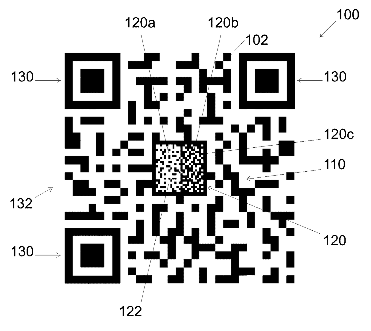
[0063]FIG. 1 shows a first example of a QR code forming a first embodiment for a 2D barcode 100 according to the invention. This 2D barcode 100 is formed by a symbol having a general square shape and comprising usual patterns of a QR code, namely three position detection pattern 130 located at three of the four corners of the QR code, and a data area 132. This data area 132 first includes primary information pattern 110 formed by a chosen arrangement of elementary cells 102, being here sets of 10×10 pixels, and shown in a non-limitative way as squares. These elementary cells 102 are coding primary information and have a size allowing most copying machines to copy the primary information pattern 110 without altering it or with such a little alteration that this pattern can be decoded correctly and there is no alteration to the information stored in the cells. Typical but non limitative size of elementary cells 102 coding primary information in the primary information pattern 110 of o...

second embodiment

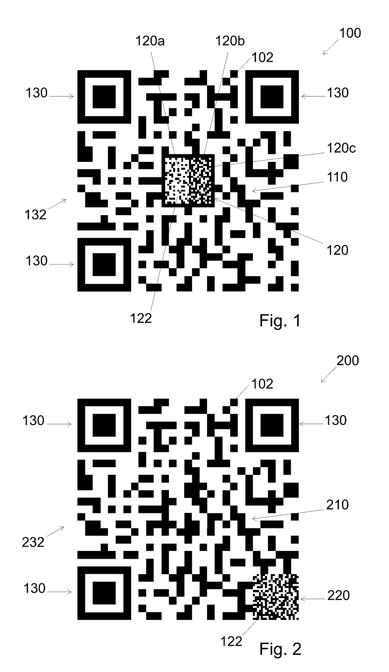
[0074]FIG. 2 shows a second example of a modified QR code forming a second embodiment for a 2D barcode 200 according to the invention. The reference numbers used to describe this 2D barcode 200 are the same as for identical parts already shown in FIG. 1 and are increased by 100 for similar parts with respect of those of FIG. 1.

[0075]Here the symbol forming the modified 2D barcode 200 is formed by a square data area 232 containing three position detection patterns 130a, primary information pattern 210, and a visible pattern 220. In this second embodiment, secondary information is embedded by a visible pattern 220 which is not located in the center area of the square data area 232 but is located at the corner of the square data area 232 which does not contain a position detection pattern 130 (here at lower right corner). This situation does not disturb the position detection function of the three position detection patterns 130 since they stay at the same place and have not been modif...

third embodiment

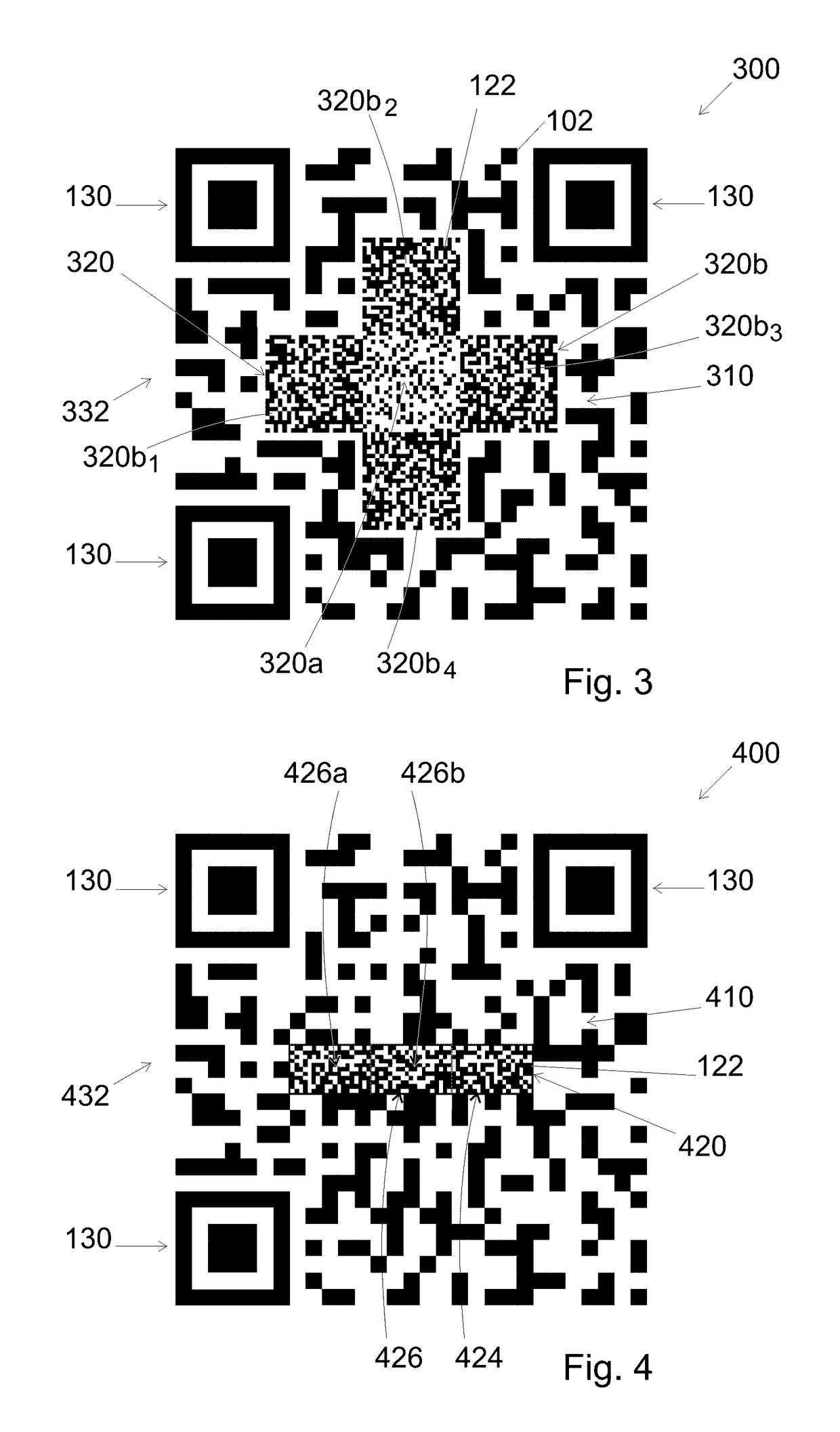
[0077]FIG. 3 shows a third example of a modified QR code forming a third embodiment for a 2D barcode 300 according to the invention. The reference numbers used to describe this 2D barcode 300 are the same as for identical parts already shown in FIG. 1 and are increased by 200 for similar parts with respect of those of FIG. 1.

[0078]As for 2D barcode 100 of FIG. 1, the 2D barcode 300 of FIG. 3 contains a visible pattern 320 with secondary information which is centered within the primary information pattern 310, which means matching between the geometrical center of the visible pattern 320 and the geometrical center of the primary information pattern 310. In this third embodiment, the visible pattern 320 is formed by a square first portion 320a having a first low average black density or first low average level of grey and being centrally located inside the visible pattern 320, and a second portion 320b with a second high average black density or second high average level of grey and s...


PUM


Abstract

A method is disclosed for creating a 2D barcode. In an embodiment, the method includes: embedding primary information that can be read by a 2D-barcode-reader in a primary information pattern, and embedding secondary information that is made difficult to reproduce without alteration in a visible pattern. In an embodiment, the visible pattern is embedded within the barcode in at least one area that does not contain any primary information.

Description

FIELD OF THE INVENTION[0001]The present invention concerns a method for creating a 2D barcode, a product embedding a 2D barcode, a method of manufacturing such product and a method of authentication of such 2D barcode. The present invention also concerns a computer implemented method for generating a 2D barcode, a non-transient computer-readable medium and a computing apparatus used for performing such method.BACKGROUND[0002]2D barcodes are data carrier used to assign a unique or batch identity to a product, document or any other item. Such 2D barcodes are preferably formed by a two-dimensional grid defining a 2D matrix whose cells are coded with information, notably binary information such as 0 or 1 coding bits which in series can code different type of characters.[0003]According to the invention all two-dimensional bar codes (2D bar codes) are concerned, and notably the very common following ones: PDF-417, MaxiCode, Datamatrix, QR Code, Aztec Code, and EAN barcodes. These barcodes...

Claims


Application Information

Patent Timeline
Patent Type & Authority Patents(United States)
IPC IPC(8): G06K19/06G06K7/14G06K7/10
CPCG06K19/06037G06K7/10722G06K7/1417G06K7/1434G06K19/06056G06K19/06075H04W12/77G07D7/0056G06K7/14G06K19/06G06K19/06028
Inventor PICARD, JUSTINLANDRY, PAUL
Owner SCANTRUST
Learn More