Rim for a pneumatic tire

a pneumatic tire and rim technology, applied in the field of rims, can solve the problems of easy cracking of the outer surface of the tire sidewall portion, and achieve the effect of suppressing local deformation of the sidewall portion and suppressing the occurrence of damage to the sidewall portion

Active Publication Date: 2015-12-22
BRIDGESTONE CORP
View PDF29 Cites 1 Cited by
  • Summary
  • Abstract
  • Description
  • Claims
  • Application Information

AI Technical Summary

Benefits of technology

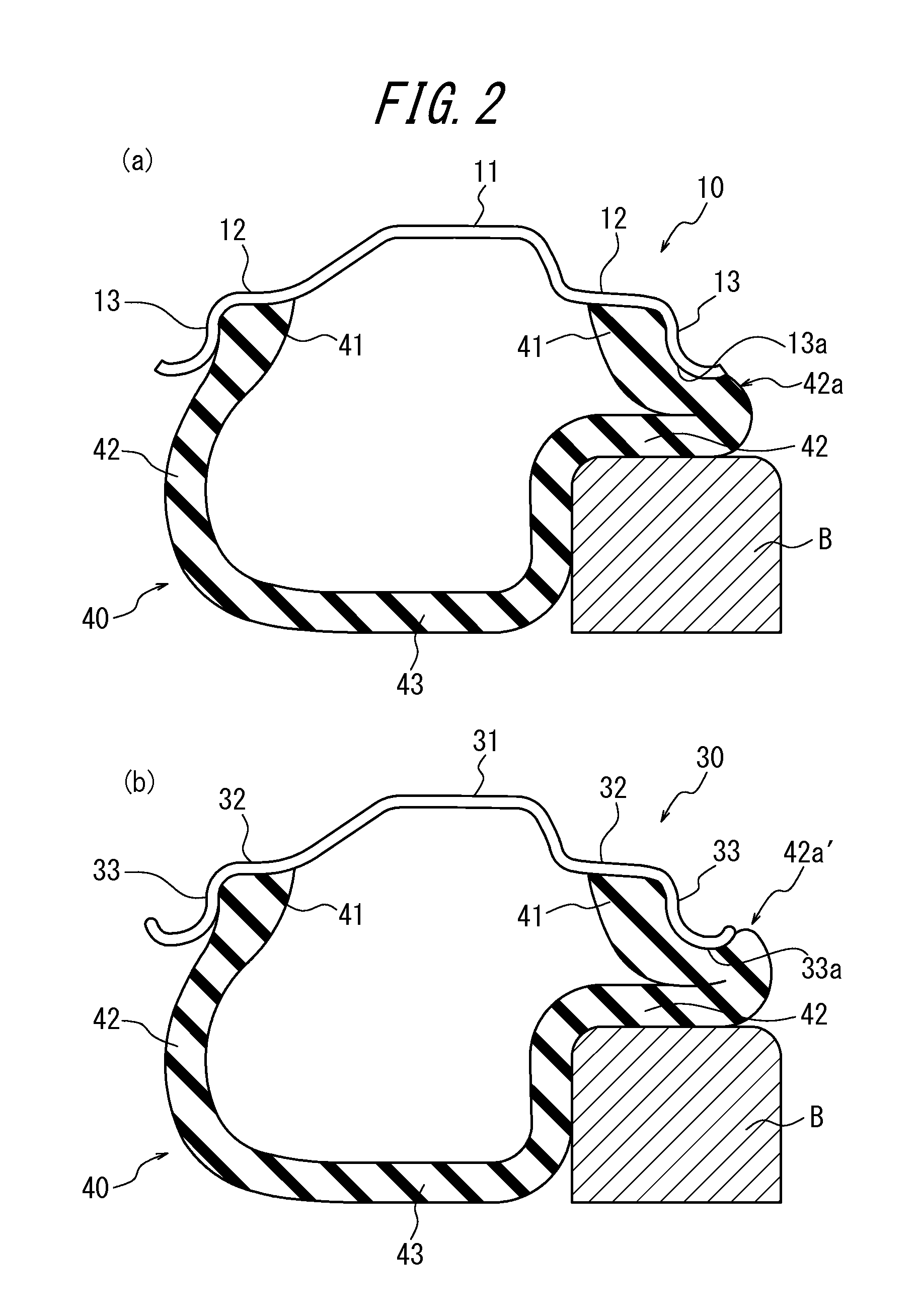
[0007]Generally, when a tire is mounted on the rim of the wheel and is run, the tire sidewall portion might deform by bending until contacting the surface of the flange portion at the rim width direction outer end portion thereof if the tire is driven onto a curb or the like. As a result, in the above conventional rim, in which the radius of curvature of the surface of the flange portion at the rim width direction outer end portion thereof is extremely small as viewed in a rim width direction cross-sectional diagram, deformation of a sidewall portion 42 when the tire 40 is driven onto a curb B or the like easily becomes locally large at a position 42a′ at which the sidewall portion 42 contacts the rim width direction outer end portion of the flange portion 33 of the rim 30, as illustrated in the rim width direction cross-sectional diagram of a tire and rim assembly in FIG. 2(b). As a result, in a tire and rim assembly using the above conventional rim, damage such as a crack on the outer surface of the tire sidewall portion easily occurs.
[0008]To address this problem, it is an object of the present invention to provide a rim for a pneumatic tire that can suppress local deformation of the sidewall portion of a rim-mounted tire and suppress the occurrence of damage to the sidewall portion even when the mounted tire is driven onto a curb or the like.
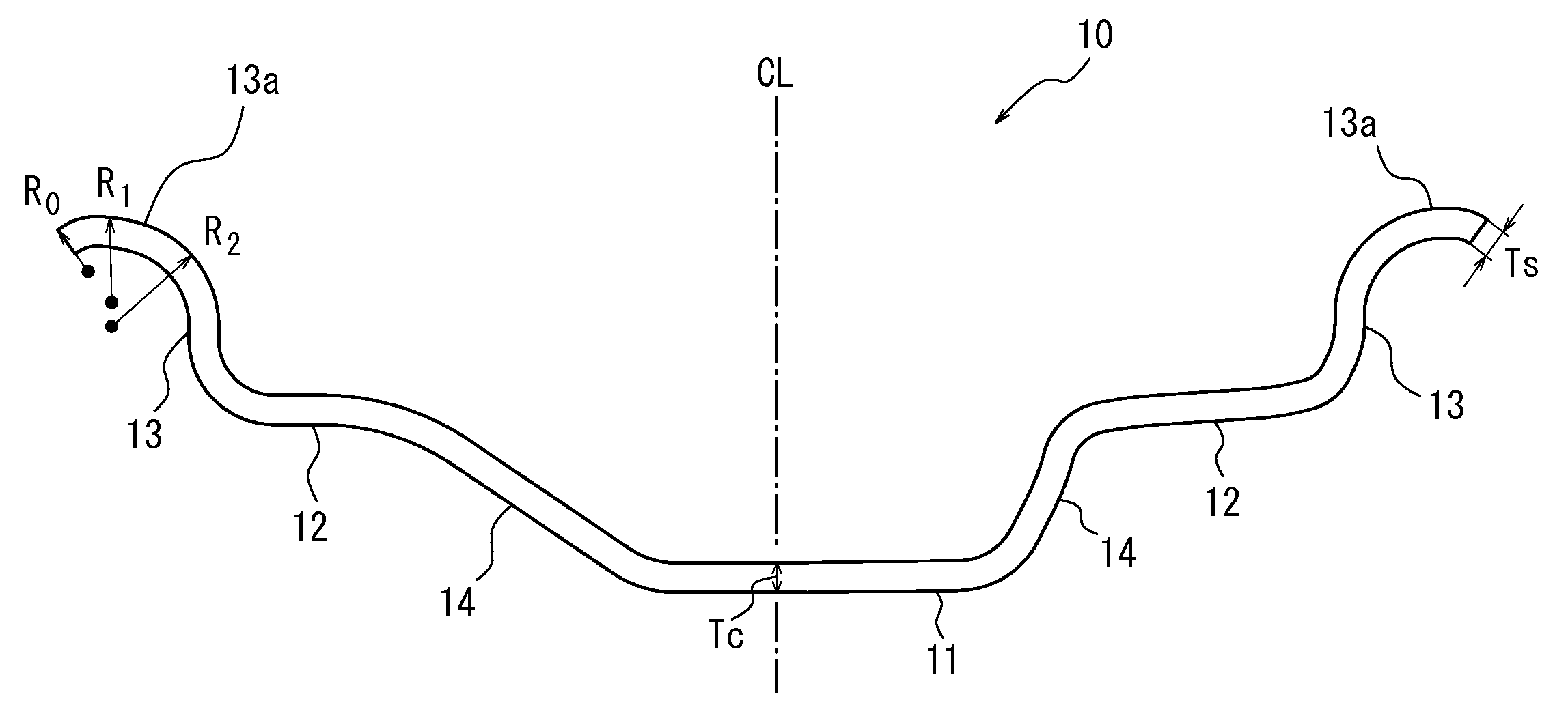
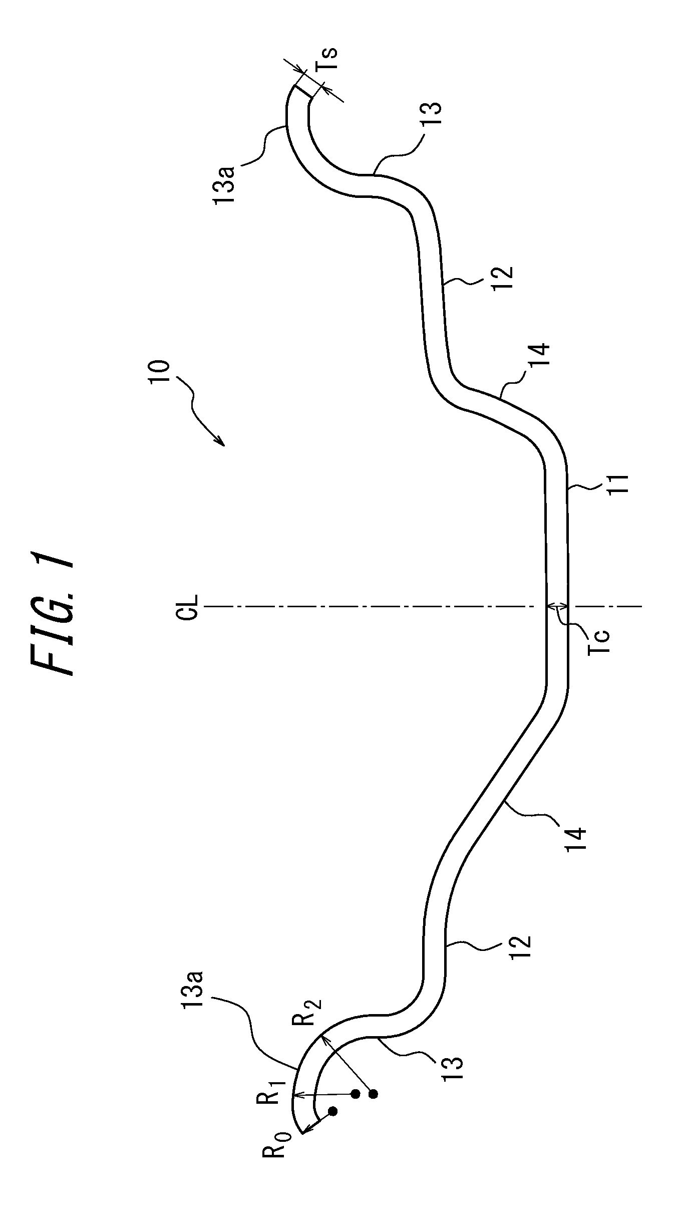
[0009]It is an object of the present invention to resolve the above problems advantageously, and a rim for a pneumatic tire according to the present invention comprises a pair of bead seat portions separated from each other in a rim width direction and a flange portion extending outwards in a rim radial direction from a rim width direction outer end of each bead seat portion, a rim radial direction outer end of the flange portion being recurved outwards in the rim width direction, wherein a radius of curvature of a surface of the flange portion at a rim width direction outer end portion of the flange portion is at least 0.4 times and at most 1.0 times a radius of curvature of the surface of the flange portion at a rim width direction central portion of the flange portion. Thus setting the radius of curvature R0 of the surface of the flange portion at the rim width direction outer end portion thereof to be at least 0.4 times the radius of curvature R1 of the surface of the flange portion at the rim width direction central portion thereof (R0 / R1≧0.4) can suppress local deformation of the sidewall portion of the rim-mounted tire even when the mounted tire is driven onto a curb or the like. Furthermore, setting the radius of curvature R0 of the surface of the flange portion at the rim width direction outer end portion thereof to be at most 1.0 times the radius of curvature R1 of the surface of the flange portion at the rim width direction central portion thereof (1.0≧R0 / R1) can guarantee a suitable gap between the flange portion and a curb or the like when the rim-mounted tire is driven onto a curb or the like, thereby suppressing deformation.
[0011]In the rim for a pneumatic tire according to the present invention, a rim thickness at a width direction center of the rim is preferably greater than the rim thickness at a width direction outer end of the rim. The reason is that if the rim thickness TC at the width direction center of the rim is thicker than the rim thickness TS at the width direction outer end of the rim, then even if the rim-mounted tire is driven onto a curb or the like, the rim itself deforms when the sidewall portion of the mounted tire contacts the flange portion of the rim, thereby suppressing the sidewall portion of the tire from penetrating to the rim width direction outer end portion of the flange portion of the rim.
[0013]In the rim for a pneumatic tire according to the present invention, the rim thickness preferably gradually decreases from the width direction center of the rim to the width direction outer end of the rim. The reason is that if the rim thickness is decreased gradually from the width direction center of the rim to the width direction outer end of the rim, then even if the rim-mounted tire is driven onto a curb or the like, the rim itself deforms when the sidewall portion of the mounted tire contacts the flange portion of the rim, thereby suppressing the sidewall portion of the tire from penetrating to the rim width direction outer end portion of the flange portion of the rim.
[0014]According to the rim for a pneumatic tire of the present invention, it is possible to suppress local deformation of the sidewall portion of a mounted tire and thus suppress the occurrence of damage to the sidewall portion.

Problems solved by technology

As a result, in a tire and rim assembly using the above conventional rim, damage such as a crack on the outer surface of the tire sidewall portion easily occurs.

Method used


Image

  • Rim for a pneumatic tire
  • Rim for a pneumatic tire
  • Rim for a pneumatic tire

Examples


example 1

Conventional Example 1

[0034]An FEM model for simulation of a rim for a pneumatic tire having a size of 7.0 J×17, the structure illustrated in FIGS. 3(a) and 3(b), and the specifications listed in Table 1 was created, and the performance thereof was assessed using the method described below. Table 1 lists the results of assessment.

example 8

[0036]An FEM model for simulation of a rim for a pneumatic tire was created to be the same as Example 5, except that the rim thickness was decreased gradually from the width direction center to the width direction outer end of the rim. Performance was then assessed with the same method as for Example 1. Table 1 lists the results of assessment. Note that the rim thickness was decreased gradually at a rate of 0.04 mm per 1 mm in the rim width direction.

Damage to Sidewall Portion

[0037]FEM models for simulation were created for tires, with a size of 215×45R17, mounted on the produced rims, and simulations were performed by pushing the tires onto a 60 cm high curb under the conditions of 230 kPa air pressure and a 10 kN load. The maximum distortion in the tire radial direction (rim radial direction) of the sidewall portion contacting the flange portion of the rim was calculated and assessed as an index with Conventional Example 1 as 100. In Table 1, a smaller index indicates less local d...


PUM


Abstract

It is an object of the present invention to provide a rim for a pneumatic tire that can suppress local deformation of the sidewall portion of a mounted tire and thus suppress the occurrence of damage to the sidewall portion. The rim for a pneumatic tire according to the present invention is provided with a pair of bead seat portions separated from each other in a rim width direction and a flange portion extending outwards in a rim radial direction from a rim width direction outer end of each bead seat portion. A rim radial direction outer end of the flange portion is recurved outwards in the rim width direction. A radius of curvature of a surface of the flange portion at a rim width direction outer end portion of the flange portion is at least 0.4 times and at most 1.0 times a radius of curvature of the surface of the flange portion at a rim width direction central portion of the flange portion.

Description

CROSS REFERENCE TO RELATED APPLICATIONS[0001]This application is a National Stage of International Application No. PCT / JP2012 / 000751 filed Feb. 3, 2012, claiming priority based on Japanese Patent Application No. 2011-023137, filed Feb. 4, 2011, the contents of all of which are incorporated herein by reference in their entirety.TECHNICAL FIELD[0002]The present invention relates to a rim on which a tire is mounted, and in particular to a rim suitable for use with a pneumatic radial tire.BACKGROUND ART[0003]A conventionally known vehicle wheel on which a tire is mounted is provided with a rim for mounting the tire and a disk attached to an axle hub provided at one side end of the rim in the rim width direction.[0004]As the rim of the wheel, a rim 30 is used, for example as illustrated in the perspective view of FIG. 3(a) and in the width direction cross-sectional diagram in FIG. 3(b). The rim 30 includes a well portion 31 with a generally cylindrical shape, a bead seat portion 32 provi...

Claims


Application Information

Patent Timeline
Patent Type & Authority Patents(United States)
IPC IPC(8): B60B21/02B60B21/10
CPCB60B21/104B60B21/026B60B21/02
Inventor NAKAYAMA, SOUTO
Owner BRIDGESTONE CORP
Why Eureka
Try Eureka