High-pressure tank

a high-pressure tank and tank body technology, applied in the direction of transportation and packaging, transportation items, transportation discharging methods, etc., can solve the problems of complicated operation of manual valves and inability to quickly discharge gas

Active Publication Date: 2015-12-22
TOYOTA JIDOSHA KK
View PDF19 Cites 3 Cited by
  • Summary
  • Abstract
  • Description
  • Claims
  • Application Information

AI Technical Summary

Benefits of technology

[0013]With this constitution, since the on-off valve is the manual valve, the on-off valve can be constituted to be compact. Since the manual operating section is arranged outside the high-pressure tank, the manual operating section can easily be accessed to operate the on-off valve.
[0016]With such a constitution, the manual operating sections are disposed so as to face each other in the high-pressure tank. In consequence, even when a part of the mobile body is largely deformed, the manual operating section comparatively little deformed on a side opposite to the largely deformed part can easily be accessed.
[0021]With this constitution, the gas discharge means can be disposed at the high-pressure tank by effectively using the connected body connected to the high-pressure tank. Since the manual operating sections are arranged outside the high-pressure tank, the manual operating section can easily be accessed.
[0027]With this constitution, since the manual operating sections are opposed to the spaces between the side members and the high-pressure tank, accessibility to the manual operating sections from the outside of the vehicle can be secured. When the side members are largely deformed, the manual operating sections capable of being opposed to a non-deformed or less deformed space can easily be accessed and operated with good operability.
[0029]According to this constitution, the manual operating sections can be operated at least from the transverse direction without being hampered by the side members. In consequence, operation directivities of the manual operating sections can appropriately be secured.
[0032]With this constitution, in a comparatively large-sized vehicle such as a bus, the high-pressure tank may be mounted on the upper part of the vehicle body. In a comparatively small-sized vehicle which is smaller than the bus, when the high-pressure tank is mounted on the rear lower part of the vehicle body, a residential space in the vehicle is easily secured.

Problems solved by technology

Therefore, when a vehicle structure around the high-pressure tank is largely deformed, an operation of the manual valve might be complicated.
Therefore, even when gas is to be discharged from the high-pressure tank with the manual valve, the gas is not easily quickly discharged.

Method used


Image

  • High-pressure tank
  • High-pressure tank
  • High-pressure tank

Examples


Embodiment Construction

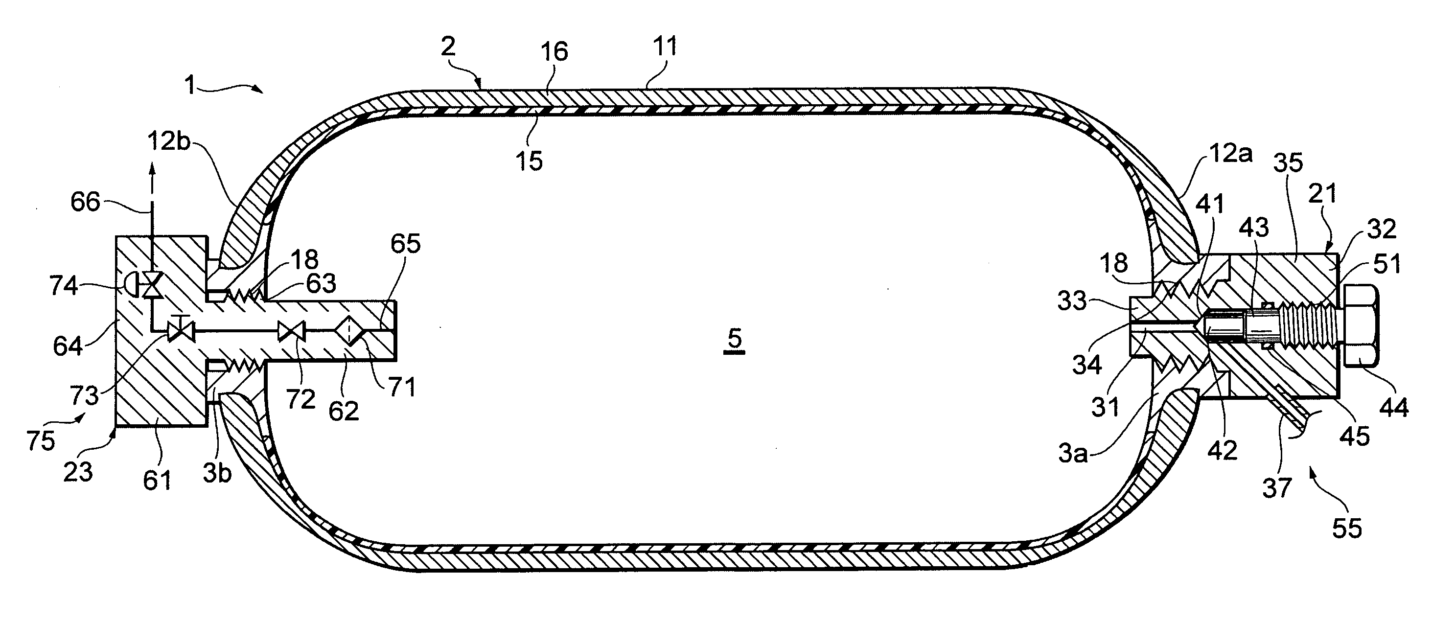
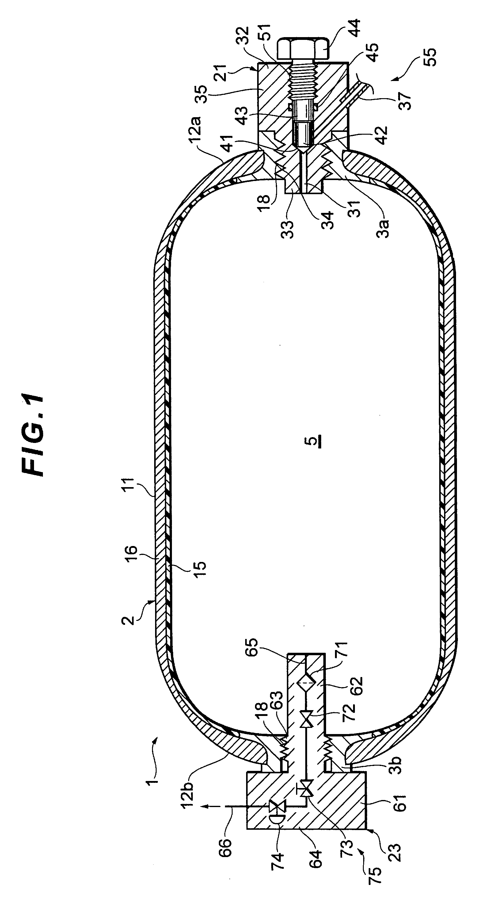
[0039]A high-pressure tank according to a preferable embodiment of the present invention will hereinafter be described with reference to the accompanying drawings. This high-pressure tank is mounted on a mobile body such as a ship or an airplane. The high-pressure tank can appropriately discharge gas stored in the high-pressure tank, even when a structure of the mobile body around the high-pressure tank is largely deformed. Here, after a structure of the high-pressure tank is described, a four-wheeled vehicle will be described as the mobile body on which the high-pressure tank is to be mounted.

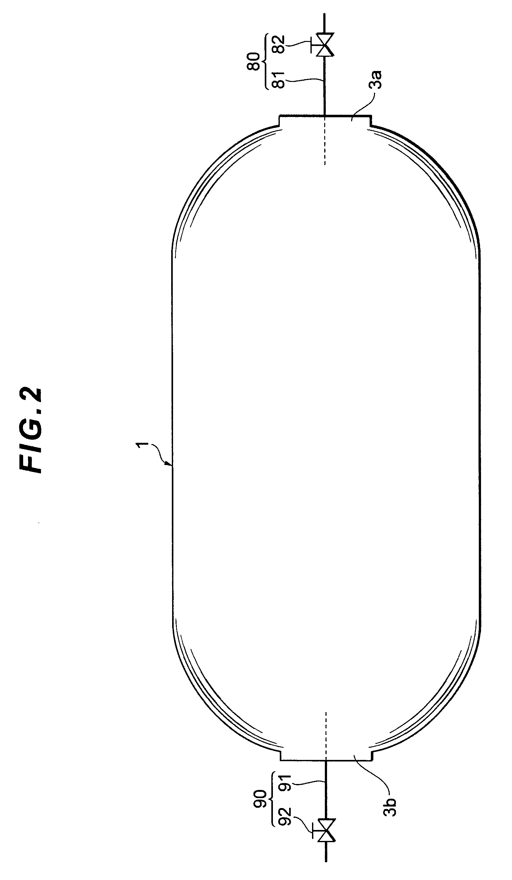
[0040]As shown in FIG. 1, a high-pressure tank 1 which is a pressure container includes a tank main body 2 having a substantially tightly closed cylindrical shape as a whole and mouth pieces 3a, 3b attached to opposite end portions of the tank main body 2 in a longitudinal direction. The inside of the tank main body 2 is a storage space 5 in which various types of gases having pressures increa...


PUM

PropertyMeasurementUnit
pressureaaaaaaaaaa
pressureaaaaaaaaaa
pressureaaaaaaaaaa

Abstract

There is disclosed a high-pressure tank capable of appropriately discharging high-pressure gas. The high-pressure tank is mounted on a mobile body, stores the high-pressure gas, and includes a plurality of gas discharge means for discharging the high-pressure gas from the high-pressure tank. The gas discharge means are disposed at opposite sides of the high-pressure tank in a longitudinal direction. The gas discharge means can each have a path through which the inside of the high-pressure tank communicates with the outside thereof, and a manual valve including a manual operating section for opening and closing the path by a manual operation.

Description

[0001]This is a 371 national phase application of PCT / JP2006 / 311460 filed 1 Jun. 2006, claiming priority to Japanese Patent Application No. 2005-161139 filed 1 Jun. 2005, the contents of which are incorporated herein by reference.TECHNICAL FIELD[0002]The present invention relates to a high-pressure tank in which gas having a pressure increased as compared with a normal pressure is stored, and more particularly, it relates to a high-pressure tank to be mounted on a mobile body such as a vehicle.BACKGROUND ART[0003]As this type of high-pressure tank, for example, a tank is known which is mounted on a rear lower part of a vehicle body of a fuel cell vehicle (see JP 2004-187485 (FIG. 14)). A pipe is connected to only one end of this high-pressure tank in a longitudinal direction, and a manual valve is installed on this pipe.DISCLOSURE OF THE INVENTION[0004]However, in a conventional high-pressure tank, the manual valve is arranged at one portion. Therefore, when a vehicle structure arou...

Claims


Application Information

Patent Timeline
Patent Type & Authority Patents(United States)
IPC IPC(8): F17C1/00H01M8/04F17C13/04B60K15/07B60K15/063
CPCF17C13/04H01M8/04216B60K15/07Y02T90/32B60K2015/0638F17C2201/0109F17C2201/035F17C2201/056F17C2203/0604F17C2203/0619F17C2203/0663F17C2205/0305F17C2205/0323F17C2205/0326F17C2205/0329F17C2205/0338F17C2205/0341F17C2205/0391F17C2205/0397F17C2221/012F17C2221/033F17C2223/0123F17C2223/036F17C2270/0105F17C2270/0168F17C2270/0189F17C2270/05H01M2250/20Y02E60/321Y02E60/50Y02E60/32Y02T90/40
Inventor ISHITOYA, TSUKUOKOBAYASHI, NOBUO
Owner TOYOTA JIDOSHA KK
Why Eureka
Try Eureka