Safety braking system for a hand-pushed rollator

a safety braking and hand-pushed technology, applied in the direction of braking systems, mechanical equipment, transportation and packaging, etc., can solve the problems of potential safety problems, difficult control of the rollator, and unsafe rollator, and achieve the effect of avoiding rollator damage, avoiding rollator damage, and avoiding rollator damag

Inactive Publication Date: 2015-12-29
DUNLAP THOMAS F
View PDF15 Cites 28 Cited by
  • Summary
  • Abstract
  • Description
  • Claims
  • Application Information

AI Technical Summary

Benefits of technology

[0009]The present invention is a safety braking system for a hand pushed wheeled rollator providing three modes of operation. The three modes of operations are a park mode for preventing the wheels from rotating, a walk mode for pushing the rollator, and a brake mode for slowing or stopping the rollator. The primary advantages of the present invention are that the user does not have to remember to set the parking brake before sitting on the rollator. Consequently, the tires are not worn out and the cable is not stretched by applying the parking brake.

Problems solved by technology

Obviously, the disadvantage of the two mode braking system is that they only have two modes of operation, which could cause safety and convenience issues.
Without a brake mode, the rollator could be difficult to control and possibly unsafe.
Other potential safety issues could also arise from using a two mode braking system.
The three mode braking system describe above also has disadvantages, which primarily stem from the spring returning the braking system to walk mode instead of park mode.
If user forgets to set the parking brake, then the rollator could unintentionally move or roll away from the user.
Typically, the parking brake compresses the tire and locks the wheel in place with a great deal of effort from the user, which is inconvenient for the user.
In addition, if the tire is worn down and / or the cable is stressed enough, the park brake may become inoperative and may require unnecessary maintenance for the rollator.

Method used


Image

  • Safety braking system for a hand-pushed rollator
  • Safety braking system for a hand-pushed rollator
  • Safety braking system for a hand-pushed rollator

Examples


Embodiment Construction

[0026]All illustrations of the drawings are for the purpose of describing selected versions of the present invention and are not intended to limit the scope of the present invention.

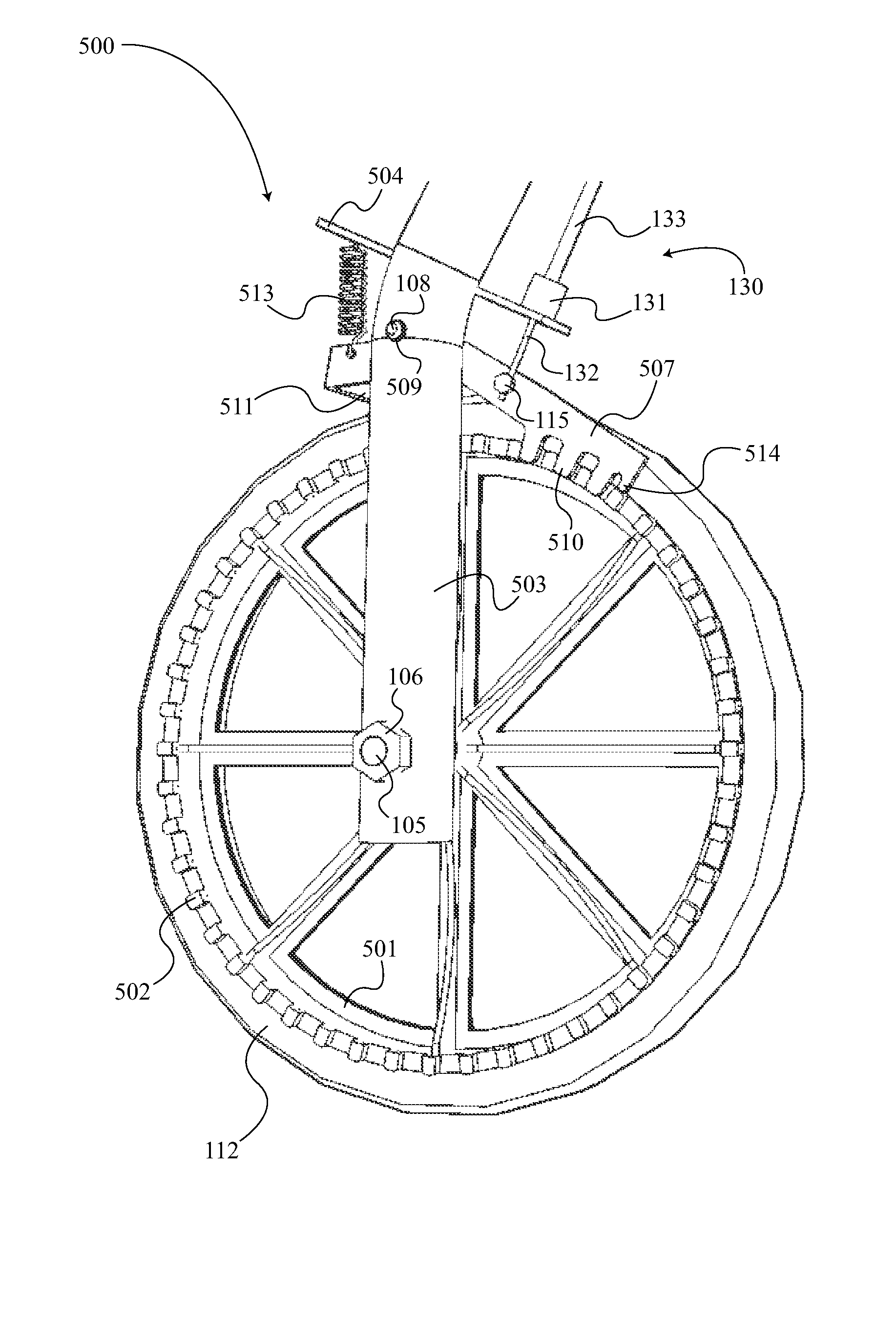
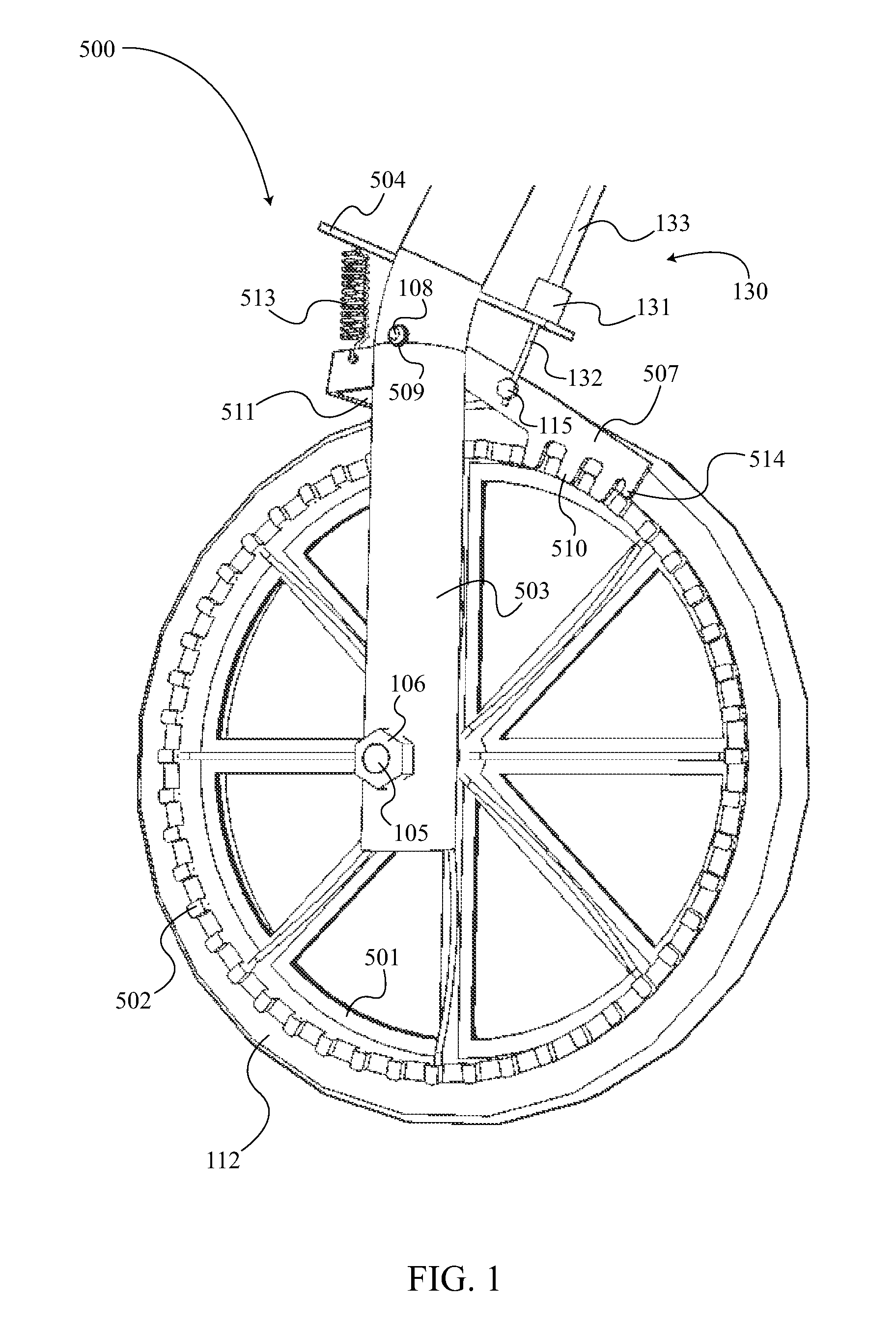
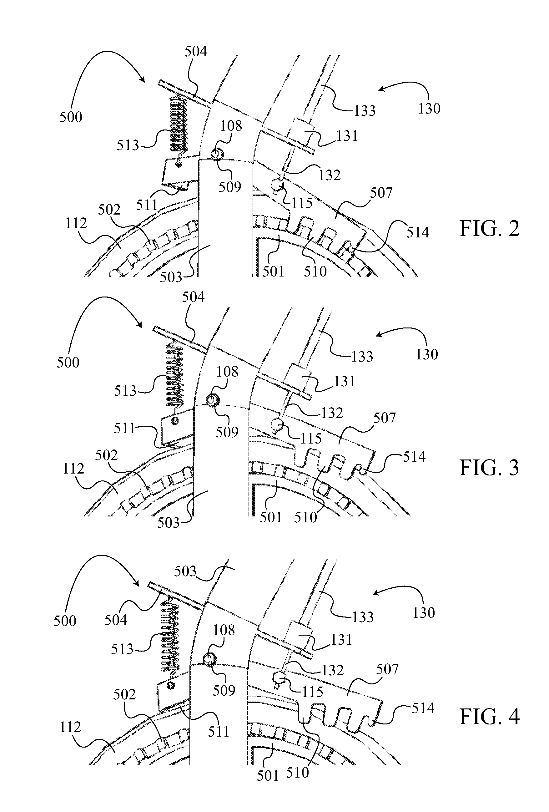
[0027]FIG. 1 shows the wheel mechanism 500 in its preferred embodiment, which comprises a wheel 501, a plurality of wheel teeth 502, a frame 503, an extension 504, an axle 105, an axle nut 106, a brake arm 507, an arm pin 108, an arm nut 509, a plurality of arm teeth 510, a friction brake 511, a tire 112, a brake system return spring 513, a stop 514, and a cable retainer 115. The wheel 501 is mounted to the frame 503 by the axle 105 and axle nut 106 so that the wheel 501 is free to rotate. The wheel 501 has a plurality of wheel teeth 502 that is concentrically connected around the wheel 501. The tire 112 encircles and is mounted onto the wheel 501. The brake arm 507 has an arm pin 108 that is mounted to pivot in the frame 503 and is secured by an arm nut 509. One side of the brake arm 507 has a plurality...


PUM


Abstract

The present invention is a safety braking system for a hand-pushed rollator, which allows the user to engage different operation modes: a park mode, a walk mode, and a brake mode. The present invention comprises a wheel mechanism, a cable assembly, and a handlebar mechanism. The wheel mechanism allows a wheel to rotate during walk mode, to engage the wheel with a parking brake during park mode, and to engage the wheel with a friction brake during brake mode. The wheel mechanism pivots the parking brake and the friction brake on a lever in order to switch between the different operation modes. The handlebar mechanism allows the user to shift between the different operation modes and is engaged to the wheel mechanism through the cable assembly. The handlebar mechanism uses two levers that are pushed and pulled by the user in order to shift between the different operation modes.

Description

[0001]The current application is a nonprovisional application and claims a priority to the U.S. provisional patent application Ser. No. 61 / 393,973 filed on Oct. 18, 2010 and U.S. provisional patent application Ser. No. 61 / 513,940 filed on Aug. 1, 2011.FIELD OF THE INVENTION[0002]The present invention generally relates to a safety braking system for a hand pushed wheeled rollator providing three modes of operation. The three modes of operation are a park mode for preventing the wheels from rotating, a walk mode for pushing the rollator, and a brake mode for slowing the rollator. For each wheel, the braking system incorporates a brake device that moves through three positions corresponding to the modes of operation. For each handlebar, the braking system incorporates a lower lever and an upper lever. The brake device is moved through the three modes of operation with a single cable by using the lower lever and the upper lever. As the user grips the lower lever, the return spring force...

Claims


Application Information

Patent Timeline
Patent Type & Authority Patents(United States)
IPC IPC(8): B60T1/00B60T1/06A61H3/04B60T1/04B60T7/10B60T11/04F16D63/00
CPCB60T1/005A61H3/04B60T1/04B60T7/104B60T11/046F16D63/006B60T1/06A61H2003/046
Inventor DUNLAP, THOMAS F.
Owner DUNLAP THOMAS F
Why Eureka
Try Eureka