Variable capacitance device

a capacitance device and variable technology, applied in variable capacitors, relays, instruments, etc., can solve the problems of difficult to control the driving voltage, the amount of signal loss due to the connection pattern cannot be ignored, and the size and space reduction is difficul

Active Publication Date: 2015-12-29
MURATA MFG CO LTD
View PDF16 Cites 3 Cited by
  • Summary
  • Abstract
  • Description
  • Claims
  • Application Information

AI Technical Summary

Benefits of technology

[0014]Preferred embodiments of the present invention provide a variable capacitance device that can reliably provide a desired capacitance even when factors that cause the capacitance to vary are generated.
[0017]This configuration utilizes the fact that there is a one to one correspondence between the capacitance of the driving capacitance portion generated by the first driving electrode and the second driving electrode and a capacitance generated by the first variable capacitance electrode and the second variable capacitance electrode that function as the opposing electrodes of the variable capacitance device. The difference between the voltage of the reference capacitor, which has been set in accordance with the capacitance of the driving capacitance portion corresponding to a desired capacitance which is to be realized by the variable capacitance device, and the voltage of the driving capacitance portion is reflected in the driving voltage, and the driving voltage is controlled so as to make the voltage difference be zero. This enables control to make the capacitance of the variable capacitance device have a desired value. The use of a pulse signal for capacitance detection at this time enables a reduction in the influence of a capacitance detection operation on the variable capacitance. That is, it takes a certain response time after the voltage is applied for the movable portion, which has a predetermined strength and a predetermined elasticity, to be displaced by an amount of displacement corresponding to the applied voltage. Hence, by making the duration of the capacitance detection pulse signal be shorter than this response time, generation of the mechanical response of the movable portion can be limited to a minimum. Further, an electric charge supplied by the pulse signal to the driving electrode is negligibly small compared with an electric charge due to the driving voltage that is actually applied for driving. Hence, there is a negligible influence of the pulse signal for capacitance detection on the actual driving of the movable portion.
[0023]By providing a sample / hold circuit in this manner, a voltage difference and a comparison result that are reliable and accurate can be obtained at a desired timing.
[0026]According to various preferred embodiments of the present invention, a desired capacitance is reliably obtained even when the factors that cause the capacitance to vary are generated in a variable capacitance device.

Problems solved by technology

As a result, reductions in size and space are difficult.
Further, the amount of signal loss due to the connection patterns cannot be ignored.
However, with existing configurations, it is actually not easy to control the driving voltage so as to maintain the capacitance at a constant value because of, for example, the aging deterioration of a movable plate, self actuation, variations in the driving voltage, and instantaneous deformation of the movable plate due to external factors.

Method used


Image

  • Variable capacitance device
  • Variable capacitance device
  • Variable capacitance device

Examples


Embodiment Construction

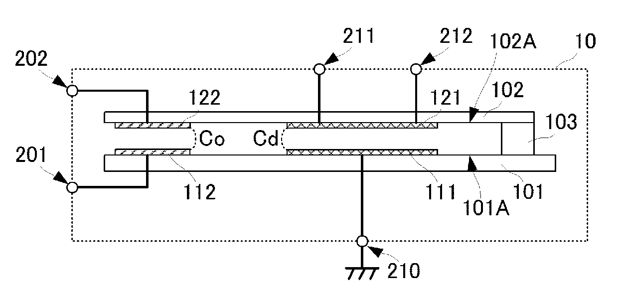
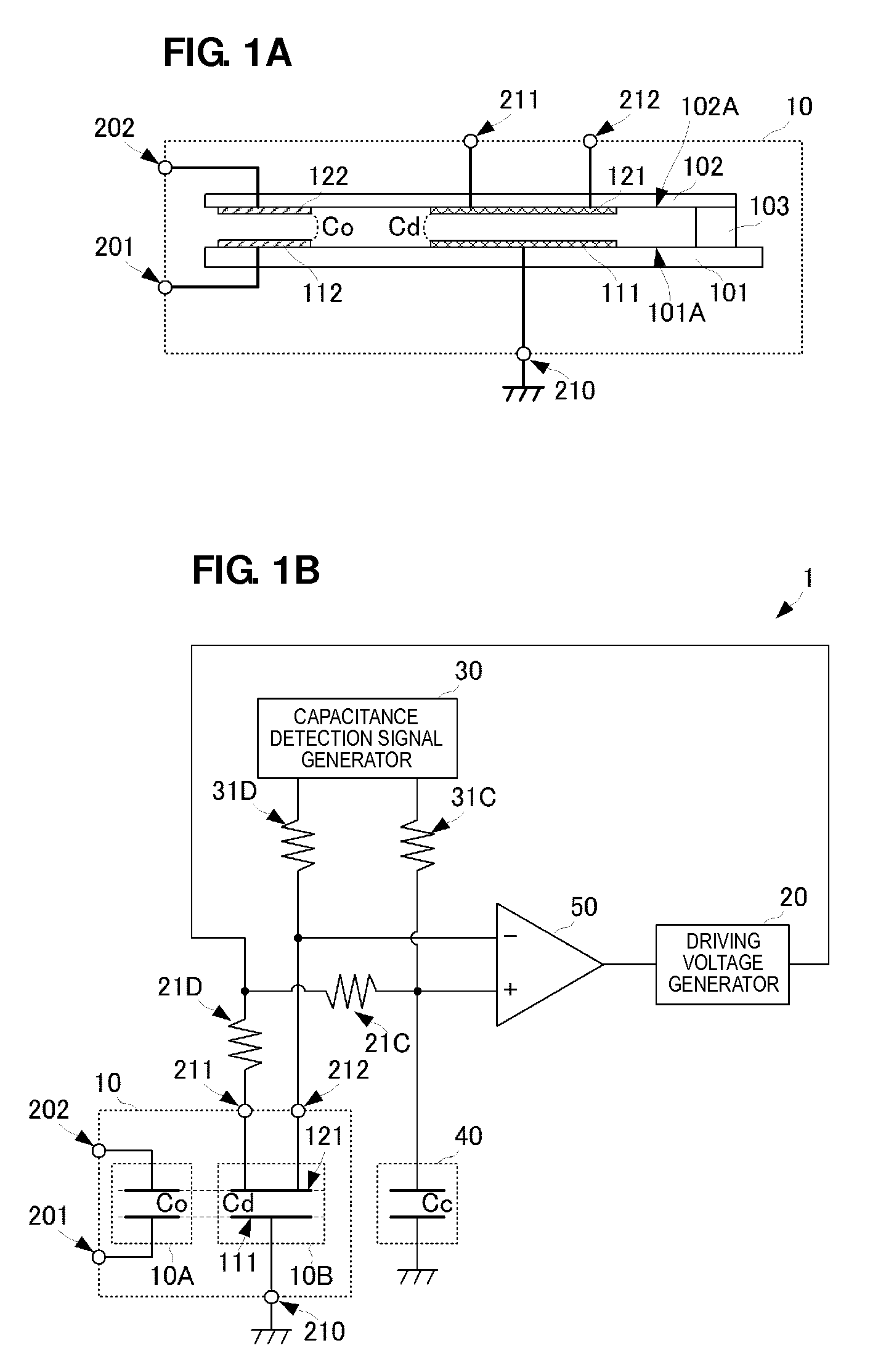
[0036]A variable capacitance device according to a first preferred embodiment of the present invention will be described with reference to the drawings. FIG. 1A is a schematic configuration diagram of a MEMS mechanical unit 10 of a variable capacitance device 1 of the present preferred embodiment, and FIG. 1B is a circuit block diagram of the entire configuration of the variable capacitance device 1.

[0037]First, the configuration of the MEMS mechanical unit 10 of the variable capacitance device 1 will be described.

[0038]The MEMS mechanical unit 10 includes a fixed plate 101, a movable plate 102, and a fixed portion 103. The fixed plate 101 and the movable plate 102 are planar plates with predetermined thicknesses. Note, however, that the movable plate 102 preferably has a thickness that allows for displacement caused by application of a driving voltage described later. The fixed plate 101 and the movable plate 102 are preferably made of a material such as silicon, and specifically i...


PUM


Abstract

A variable capacitance device that achieves a desired capacitance even when factors causing varied capacitances are generated is configured such that a capacitance detection pulse signal is applied from a capacitance detection signal generation unit to a driving capacitor and a reference capacitor of a MEMS mechanical unit. The device voltage of the driving capacitor based on the capacitance detection signal and a driving voltage is applied to the inverting input terminal of a comparator. The device voltage of the reference capacitor based on the capacitance detection signal and the driving voltage is applied to the non-inverting input terminal of the comparator. The comparator generates a comparison output signal including “Hi” and “Low” values from the difference between these device voltages, and applies the output signal to a driving voltage generation unit. The driving voltage generation unit increases or decreases the driving voltage based on the comparison output signal.

Description

BACKGROUND OF THE INVENTION[0001]1. Field of the Invention[0002]The present invention relates to variable capacitance devices including a MEMS structure, and specifically to variable capacitance devices that include a control circuit that electrically controls a distance between opposing electrodes.[0003]2. Description of the Related Art[0004]Currently, many attempts are being made to apply variable capacitance devices that use a MEMS structure to, for example, matching circuits in the front end portions of wireless communication high-frequency modules for cellular phones.[0005]A variable capacitance device that uses a MEMS structure includes a mechanical unit that actually functions as a variable capacitance device and a driving circuit that applies a driving voltage to the mechanical unit, as described in Japanese Unexamined Patent Application Publication No. 2008-181725 and Japanese Unexamined Patent Application Publication No. 2009-70940.[0006]The mechanical unit includes a fixe...

Claims


Application Information

Patent Timeline
Patent Type & Authority Patents(United States)
IPC IPC(8): H01G5/00H01H57/00G01R27/26H01G5/16H01G7/06H01G7/00H03J3/20
CPCH01G5/16H03J3/20H03J2200/19
Inventor KUMADA, AKIRASHIBAHARA, TERUHISATANAKA, KENJI
Owner MURATA MFG CO LTD
Why Eureka
Try Eureka