Actuator with quick-release mechanism

a quick-release mechanism and actuator technology, applied in the direction of mechanical equipment, belts/chains/gearrings, etc., can solve the problems of increasing the overall production cost of the actuator, the inconvenience of the use and operation of the actuator, and the material and manufacturing costs of the actuator, so as to reduce the required pulling force and ensure the transmission between the worm gear and the worm shaft.

Active Publication Date: 2016-01-05
TIMOTION TECH CO LTD
View PDF14 Cites 3 Cited by
  • Summary
  • Abstract
  • Description
  • Claims
  • Application Information

AI Technical Summary

Benefits of technology

[0007]An objective of the present invention is to provide an actuator with a quick-release mechanism which is of an overall structure of a simplified design such that the assembly process and operation thereof can be made convenient and facilitated.
[0010]The present invention is of the following merits and technical effects. During the release process of the second cylinder and the worm gear assembly, since the worm gear assembly is not subject to any lateral pushing forces exerted by the rotating piece, the worm gear assembly is free from shifting of positions such that a stable transmission between the worm gear and the worm shaft can be ensured. By locking the pulling rod onto the rotating piece, the arc swing movement is translated into a linear motion, which greatly reduces the required pulling force to be exerted by the user.

Problems solved by technology

Such known actuator is of a complicated structure involving a great number of components, which poses difficulties to the assembly thereof and requires greater costs in the material and manufacturing the components as well as the overall production costs of the actuator.
Furthermore, the method of push used to actuate the engagement and disengagement of the cylindrical connection parts tends to generate a relatively small reaction force, which leads to inconvenience to the use and operation of the actuator.

Method used


Image

  • Actuator with quick-release mechanism
  • Actuator with quick-release mechanism
  • Actuator with quick-release mechanism

Examples


Embodiment Construction

[0019]The following provides a detailed description of the technical features of the present invention along with the accompanied drawings. It can however be understood that the accompanied drawings are provided for illustrative purposes only and shall not be used as a limitation to the present invention.

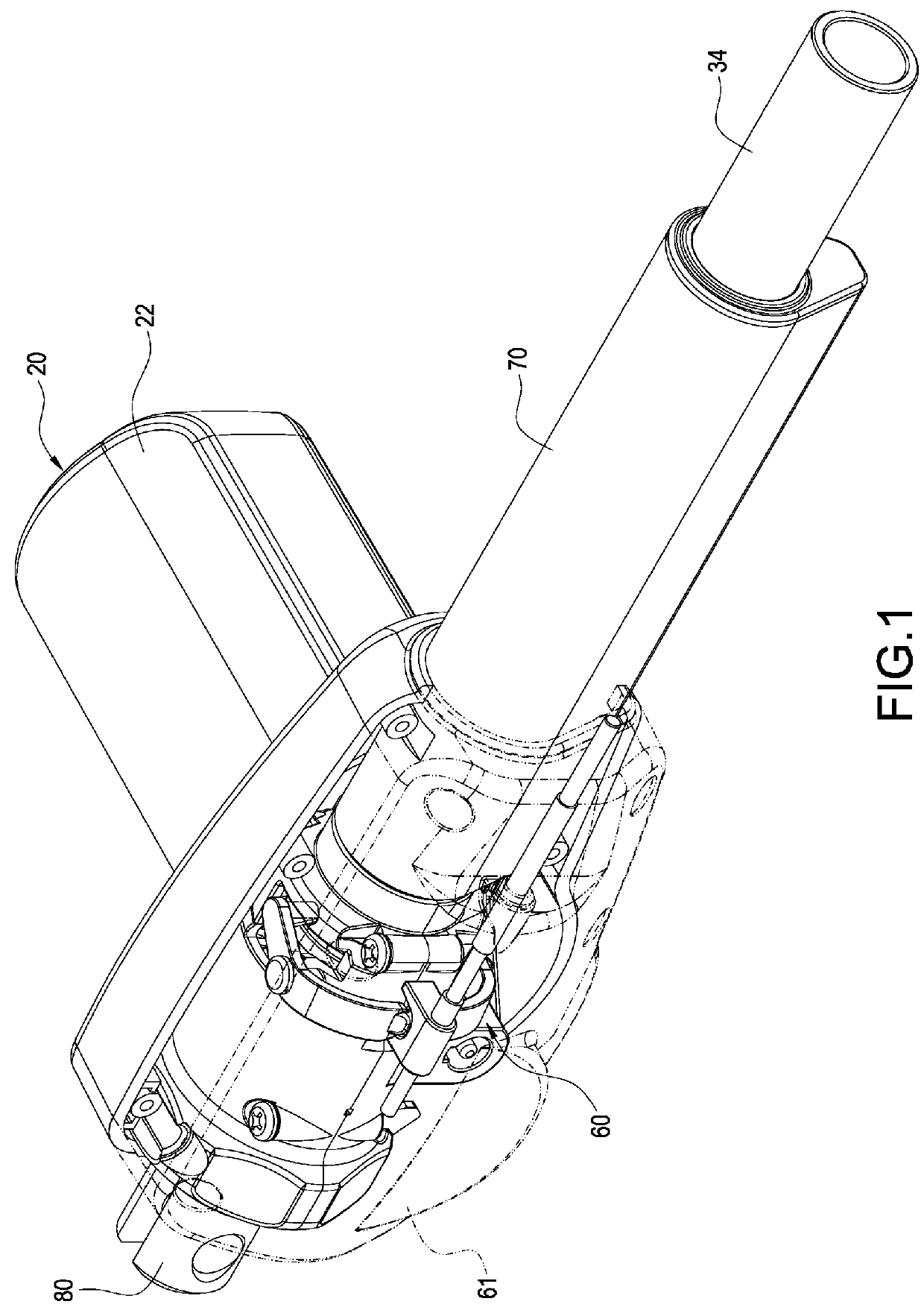
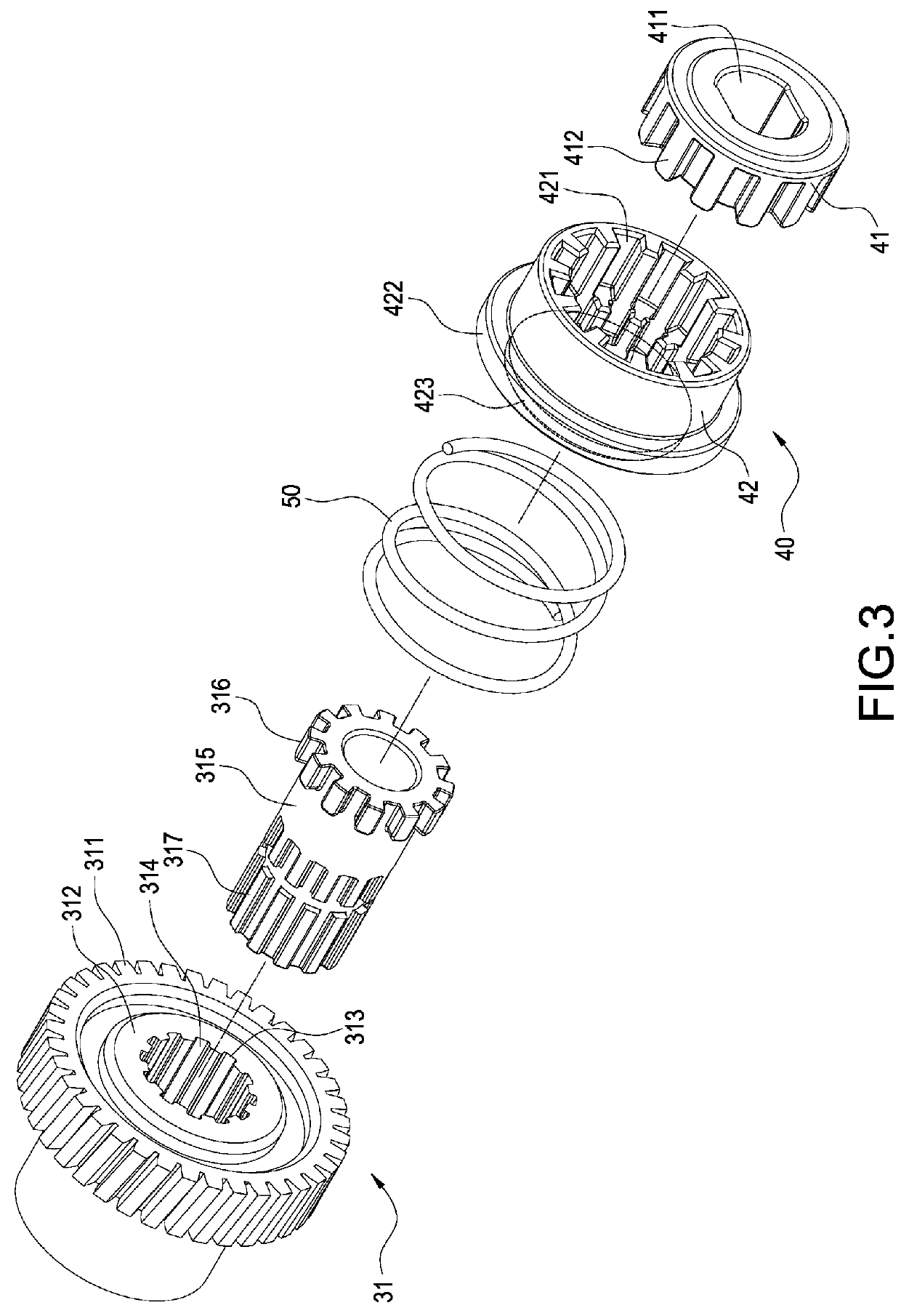
[0020]Please refer to FIG. 1 to FIG. 5. As shown in the figures, the present invention provides an actuator with a quick-release mechanism comprising a base 10, an electric motor 20, a transmission mechanism 30, a quick-release mechanism 40, an elastic member 50 and a dialing mechanism 60.

[0021]The base 10 comprises a lower base part 11 and an upper base part 12 closed correspondingly onto the lower base part 11. A chamber 13 is formed between the upper base part 12 and the lower base part 11. In addition, the upper base part 12 and the lower base part 11 are fastened with each other via fastening means such as screws. The lower base part 11 and the upper base part 12 comprise a pai...


PUM


Abstract

An actuator with a quick-release mechanism includes a base (10); an electric motor (20) including a worm shaft (212); a transmission mechanism (30) including a worm gear assembly (31), a lead screw shaft (32) and a bearing (33); a quick-release mechanism (40) including first and second cylinders (41, 42) attached to the lead screw shaft (32); an elastic member (50) clamped between the worm gear assembly (31) and the second cylinder (42) and a dialing mechanism (60) including a rotating piece (62) pivotally attached to the base (10); and wherein the worm gear assembly (31) including protruding teeth (316); the second cylinder (42) includes teeth slots (424) engaged with the protruding teeth (316) for engaged or disengaged transmission; and the rotating piece (62) includes a dial arm (621) to push the second cylinder (42) to disengage from the worm gear assembly (31) for torque transmission.

Description

BACKGROUND OF THE INVENTION[0001]1. Field of the Invention[0002]The present invention relates to an actuator, in particular, to an actuator with a quick-release mechanism.[0003]2. Description of Related Art[0004]Linear actuators are commonly used in applications such as electric medical beds, treadmills and wheelchairs for adjusting and shifting the elevation positions and elevation angles thereof. For emergency purposes of patient treatments, the use of actuator with a quick-release mechanism allows the medical bed to be adjusted and shifted rapidly such that precious time crucial in medical emergencies can be saved, which is an important objective of the present invention.[0005]A known actuator with a quick-release mechanism is disclosed in such as Chinese Patent Publication No. CN100552263C comprising an electric motor, a transmission mechanism and a quick-release mechanism. The electric motor comprises a main body and a worm shaft extended outward from a center of the main body....

Claims


Application Information

Patent Timeline
Patent Type & Authority Patents(United States)
IPC IPC(8): F16H25/20
CPCF16H25/20F16H2025/209F16H2025/2031F16H2025/2071F16H2025/2084Y10T74/18576
Inventor WU, CHOU-HSIN
Owner TIMOTION TECH CO LTD
Why Eureka
Try Eureka