In-water discharging core and sterilizing water supplying system using said core

a technology of in-water discharging core and water supply system, which is applied in the direction of liquid fuel feeder, peroxide/peroxyhydrate/peroxyacid/superoxide/ozonide, liquid fuel feeder, etc., can solve the problem of difficult to dissolve the generated ozone into the water, low efficiency and large operation power consumption, etc. problem, to achieve the effect of excellent quality of sterilized water and maximum sterilizing effect and operation efficiency

Inactive Publication Date: 2006-06-29
KIM ANDERSONH
View PDF2 Cites 0 Cited by
  • Summary
  • Abstract
  • Description
  • Claims
  • Application Information

AI Technical Summary

Benefits of technology

[0005] Accordingly, in order to overcome the aforementioned conventional problems, the underwater discharging cells having the imaginary intersections “Virtual Meshed Points” are developed in the present invention. The purpose of the present invention is to provide an underwater discharging core that enables to maximize the sterilizing effect by maintaining the stabile production of ozone. The assembly process for producing the underwater discharging core is also simplified and easy.
[0011] As discussed above, the underwater discharging core which utilizes the discharging cells with the imaginary wire meshes of “Virtual Meshed Points” to maximize the sterilizing effect and operating efficiency.
[0012] Therefore, it is possible to offer the excellent quality of sterilized water by adopting the sterilized water generator utilizing the underwater discharge core and a sterilized water supply system utilizing the sterilized water generator.

Problems solved by technology

Those conventional means have disadvantages of heavy weight, bulky size, lower efficient and large power consumption in operation.
Especially, the air discharging means has disadvantage that it is very hard to dissolve the generated ozone into the water (H2O).
Furthermore, it is difficult to uniformly dissolve the ozone into the water.
Because the gaseous ozone is concentrated, it is harmful to the environment and human being.

Method used


Image

  • In-water discharging core and sterilizing water supplying system using said core
  • In-water discharging core and sterilizing water supplying system using said core
  • In-water discharging core and sterilizing water supplying system using said core

Examples


first embodiment

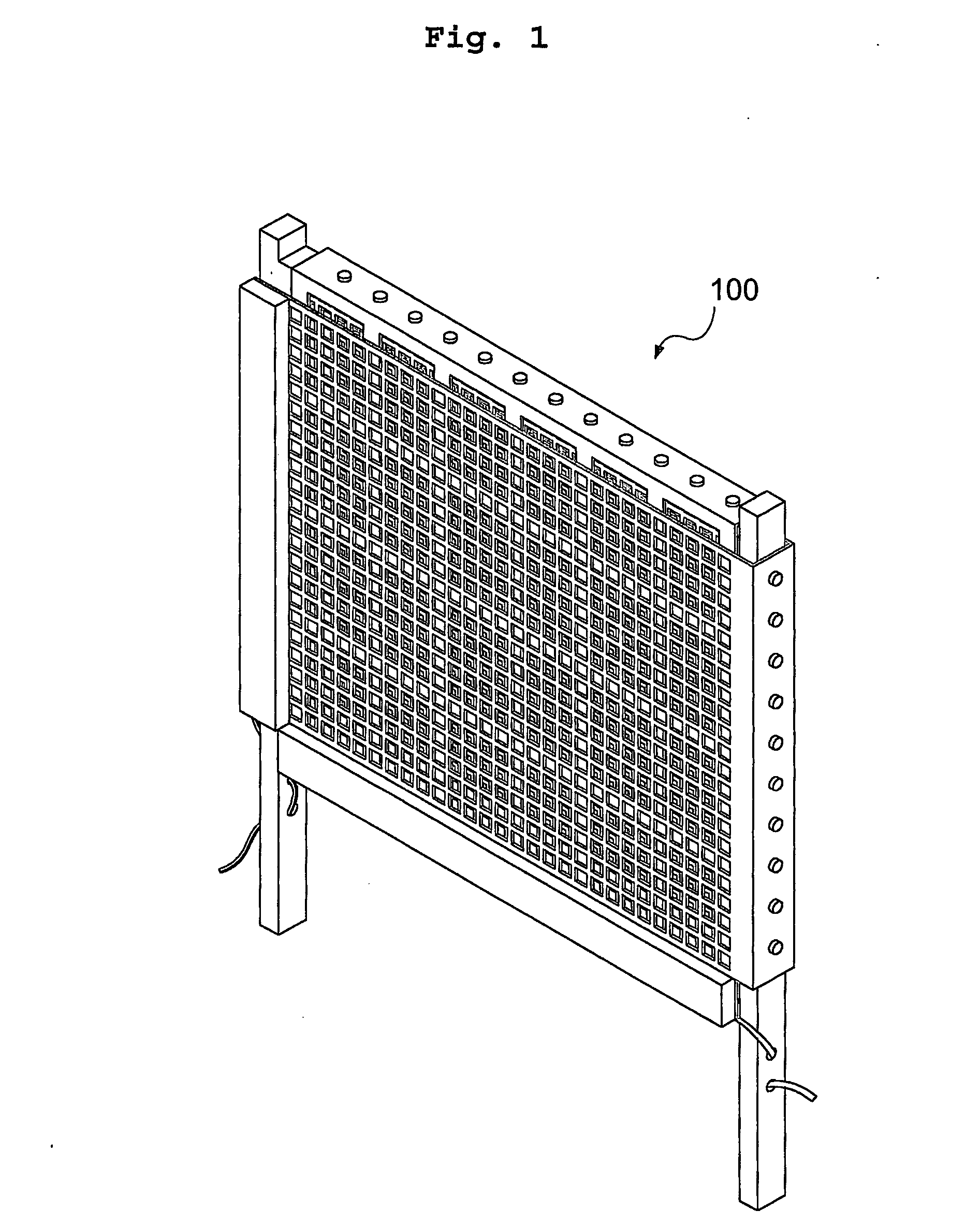
[0049] As shown in FIG. 1, an underwater discharging core (100) is presented according to the present invention. Further, FIGS. 2 through 16, the configuration and assembly of the underwater discharging core (100) are illustrated.

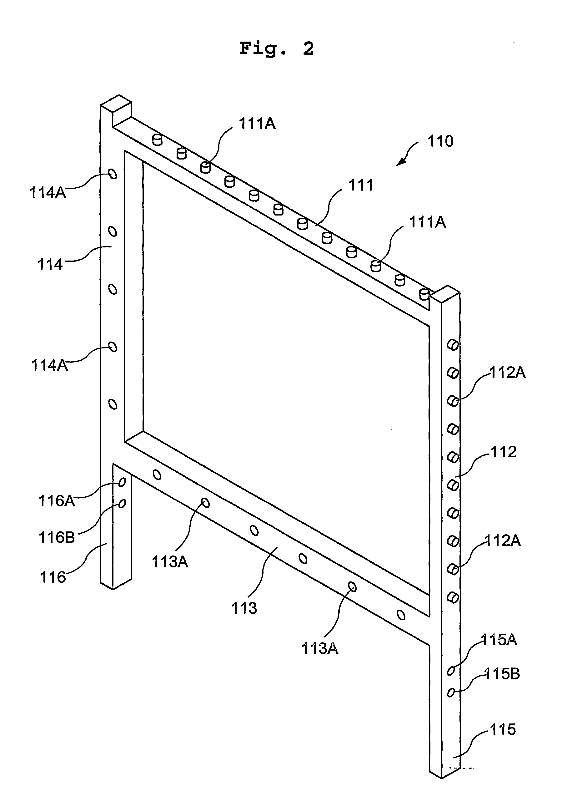
[0050] As shown in FIG. 2, a frame for installing the underwater discharging core is presented according to the first embodiment of the present invention. The frame (110) made of polycarbonate forms a rectangle shape with the two supporting legs. The frame (110) comprises an upper bar (111), a lower bar (113), a right bar (112) and a left bar (114). On top surface of the upper bar (111), it forms a plurality of protrusions (111A). The first surface of the lower bar (113), it forms a plurality of drilled holes (113A). The second surface of the right bar (112), it forms a plurality of protrusions (112A). The first surface of the left bar (114), it forms a plurality of drilled holes (114A). The right supporting leg (115) is integrally extended from the right b...

second embodiment

[0092] As shown in FIG. 19, an alternative underwater discharging core (300) is presented according to the present invention. Herein, FIGS. 20 through 24, the configuration and assembly of the alternative underwater discharge core are illustrated.

[0093] As shown in FIG. 20, a frame for installing the alternative underwater discharging core is presented according to the second embodiment of the present invention. The frame (310) made of the heat resistance material, such as a polycarbonate forms a rectangle shape with the two supporting legs. The frame (310) comprises an upper bar (311), a lower bar (314), a right bar (312) and a left bar (313). The first surface of the right and left bars (312, 313), it forms a plurality of drilled holes (312A, 313A). The right supporting leg (315) is integrally extended from the right bar (312). The left supporting leg (316) is integrally extended from the left bar (313).

[0094] As shown in FIG. 21, a first platinum plate mesh is presented for inst...

third embodiment

[0106] Referring to FIGS. 25 to 30, another alternative underwater discharging core (430) is presented according to the present invention. The configuration and assembly of the third alternative underwater discharge core are illustrated as follows.

[0107] As shown in FIG. 26, a frame for installing the third alternative underwater discharge core is presented according to the third embodiment of the present invention. The frame (410) made of the heat resistance material, such as a polycarbonate forms a rectangle shape with the two supporting legs. The frame (410) comprises an upper bar (411), a lower bar (414), a right bar (412) and a left bar (413). The first surface of the right and left bars (412, 413), it forms a plurality of drilled holes (412A, 413A). The right supporting leg (415) is integrally extended from the right bar (412). The left supporting leg (416) is integrally extended from the left bar (413).

[0108] As shown in FIG. 27, a first platinum plated mesh is presented for...


PUM

PropertyMeasurementUnit
thicknessaaaaaaaaaa
thicknessaaaaaaaaaa
thicknessaaaaaaaaaa

Abstract

An underwater discharging core that is equipped with a pair of the platinum plate meshes is developed to produce the sterilized water. The underwater discharging cells are designed based on the concept of the imaginary wire meshes of “Virtual Meshed Points” to maximize the sterilizing effect and operating efficiency. Thus, it is possible to offer the excellent quality of sterilized water by adopting the sterilized water generator utilizing the underwater discharge core and a sterilized water supply System utilizing the sterilized water generator.

Description

1. TECHNICAL FIELD [0001] The present invention is related to an underwater discharging core equipped with a pair of the platinum plate meshes made of conductive material and its application to the sterilized water supply system. 2. BACKGROUND ART [0002] Generally, the ozone generating devices, which are presently utilized, are classified into three major categories of air discharging means, infrared means and water dissolving means. Those conventional means have disadvantages of heavy weight, bulky size, lower efficient and large power consumption in operation. [0003] Especially, the air discharging means has disadvantage that it is very hard to dissolve the generated ozone into the water (H2O). Furthermore, it is difficult to uniformly dissolve the ozone into the water. When the gaseous ozone is injected into water for dissolving, approximately 50% of the ozone would be bounced out to the air. Because the gaseous ozone is concentrated, it is harmful to the environment and human be...

Claims


Application Information

Patent Timeline
Patent Type & Authority Applications(United States)
IPC IPC(8): B01D21/30C02F1/461C02F1/467C02F1/78
CPCC01B13/0207C01B13/11C01B15/027C02F1/4608C02F1/46114C02F1/4672C02F1/78C02F2001/46133C02F2001/46157C02F2201/46125C02F2209/02C02F2209/42C02F2305/023
Inventor KIM, ANDERSONH
Owner KIM ANDERSONH
Why Eureka
Try Eureka