Variable height arm structures, systems, and methods

a variable height, arm technology, applied in the field of mechanical arms, can solve the problems of poor cleaning ability poor adjustment and heavy use of arms, and poor cleaning efficiency of exposed mechanical structures, so as to improve height or counterbalancing adjustment, the effect of improving the cleanability

Active Publication Date: 2016-01-05
GCX CORP
View PDF65 Cites 20 Cited by
  • Summary
  • Abstract
  • Description
  • Claims
  • Application Information

AI Technical Summary

Problems solved by technology

However, many prior mechanical arms often include structures, e.g. such as but not limited to covers, fasteners, trim, and / or pivots, that are readily contaminated, such as by dirt, dust, grease, germs, blood, sweat, chemicals, and / or other materials.
As well, such exposed mechanical structures are not highly or thoroughly cleanable.
As well, while some prior mechanical arms have provided adjustable height, such arms are not typically designed for frequent adjustment and heavy use.
For many such structures, screen movement is typically sloppy, and joints loosen quickly.
Furthermore, such designs typically include pinch points and / or exposed gaps, which are not readily cleanable.
While some prior conventional mechanical arms have provided some adjustability over a range of angles, such designs do not offer high performance over a full range of positions.
For example, while a mechanical arm may be adjusted to provide adequate support within a central region of a range of motion for a monitor, adjustment of such an arm at a point toward the top of the range of motion often results in travel back downward towards center, unless friction of the assembly is increased to retain the monitor at the desired high position.
Similarly, adjustment of such an arm at a point toward the bottom of the range of motion often results in travel back upward towards center, unless friction of the assembly is increased to retain the monitor at the desired low position.

Method used


Image

  • Variable height arm structures, systems, and methods
  • Variable height arm structures, systems, and methods
  • Variable height arm structures, systems, and methods

Examples


Embodiment Construction

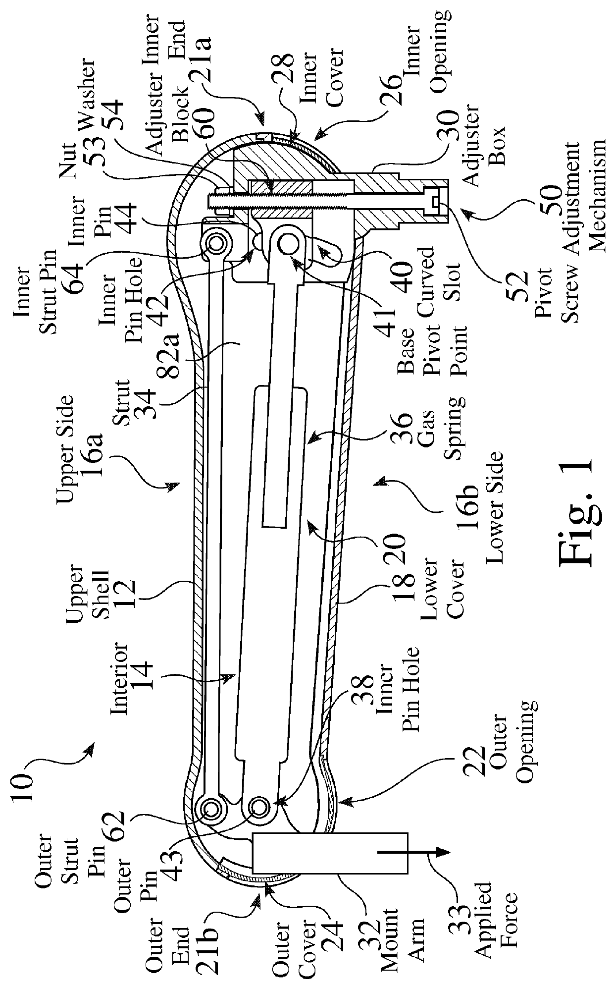
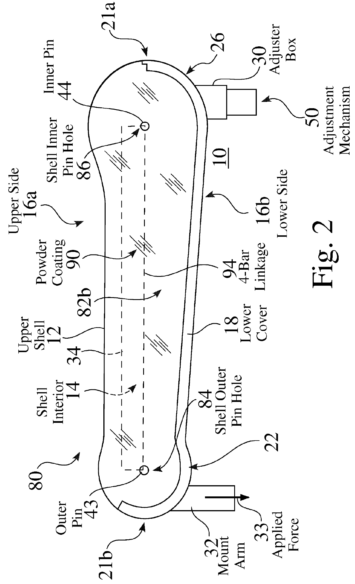
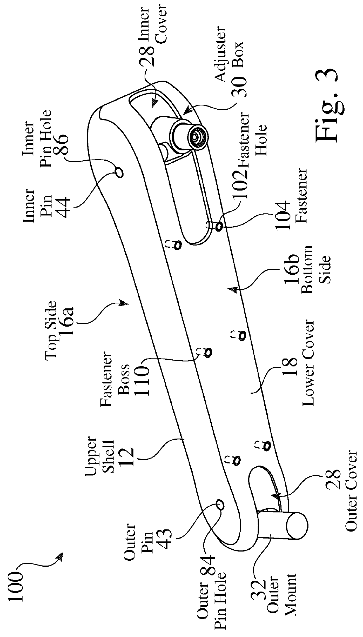
[0032]FIG. 1 is a partial side cutaway view of an exemplary enhanced variable height arm 10, which may preferably comprise a gas spring counter□balanced height adjustable arm 10. FIG. 2 is a side view 80 of an exemplary enhanced variable height arm 10. FIG. 3 is a lower perspective view 100 of an exemplary enhanced variable height arm 10. The exemplary enhanced variable height arm 10 seen in FIG. 2 and FIG. 3 may preferably comprise an outer structure 12 that prevents contamination and allows cleanability, such as for installation within a hospital environment. The enhanced variable height arm 10 is typically configured for and implemented within an arm system 300, e.g. 300a (FIG. 14), such as for but not limited to support for a monitor 252 (FIG. 10).

[0033]As seen in FIG. 1, an enhanced arm strut structure 20 extends from a first inner end 21a toward a second outer end 21b, between an adjuster box 30 and a mount arm 32. The mount arm 32 is suspended from the adjuster box 30 by a st...


PUM


Abstract

Enhanced variable-height mounting arms comprise structures that allow any of improved cleanability and / or improved adjustment of height or counterbalancing. An exemplary enhanced variable-height arm comprises an upper shell structure that substantially extends over the upper and side regions of the mounting arm, forming a four-bar linkage. A lower cover is mounted to the upper cover across the bottom side of the arm, and defines holes therethrough for extension of the opposing ends of the arm. The variable-height arm further comprises a bias element, wherein one end of the bias element is adjustably fixable in relation to a defined curve, non-linear path or slot, such as within a curved slot. The variable-height arm may preferably further comprise a mechanism for adjusting any of the height or counterbalance for the structure.

Description

FIELD OF THE INVENTION[0001]The present invention relates to the field of mechanical arms. More particularly, the present invention relates to improved variable height mechanical arm structures and processes.BACKGROUND OF THE INVENTION[0002]Mechanical arms are often used to support a wide variety of devices, such as but not limited to display screens, touch screens or monitors. Such mechanical arms may often provide any of stationary, adjustable and / or movable support, wherein positioning or movement may provide lateral movement, rotation, tilt, and / or variation of height.[0003]Mechanical arms are often used in a wide variety of biologically sensitive environments, such as but not limited to hospitals, laboratories, medical and / or dental offices, and hospices. However, many prior mechanical arms often include structures, e.g. such as but not limited to covers, fasteners, trim, and / or pivots, that are readily contaminated, such as by dirt, dust, grease, germs, blood, sweat, chemicals...

Claims


Application Information

Patent Timeline
Patent Type & Authority Patents(United States)
IPC IPC(8): A47F5/00F16M11/04F16M11/08F16M11/20F16M11/42F16M13/02F16M11/24
CPCF16M13/02F16M11/046F16M11/048F16M11/08F16M11/2014F16M11/2092F16M11/24F16M11/42F16M2200/041F16M2200/04
Inventor BORLOZ, PAUL RENELITTLEFIELD, JOSHUA KAWARIIDAUGBJERG, CRISTIAN J.
Owner GCX CORP
Why Eureka
Try Eureka