Architecture of single substrate ultrasonic imaging devices, related apparatuses, and methods

a technology of ultrasonic imaging and architecture, applied in the direction of mechanical vibration separation, acoustic wave reradiation, pulse technique, etc., can solve the problems of non-uniformity, non-scalability of machining and wiring, and prone to cost, so as to facilitate the integration of a substantial portion

Active Publication Date: 2016-01-05
BFLY OPERATIONS INC
View PDF207 Cites 79 Cited by
  • Summary
  • Abstract
  • Description
  • Claims
  • Application Information

AI Technical Summary

Problems solved by technology

Such processes are prone to the cost, non-uniformity, and non-scalability of machining and wiring.

Method used


Image

  • Architecture of single substrate ultrasonic imaging devices, related apparatuses, and methods
  • Architecture of single substrate ultrasonic imaging devices, related apparatuses, and methods
  • Architecture of single substrate ultrasonic imaging devices, related apparatuses, and methods

Examples


Embodiment Construction

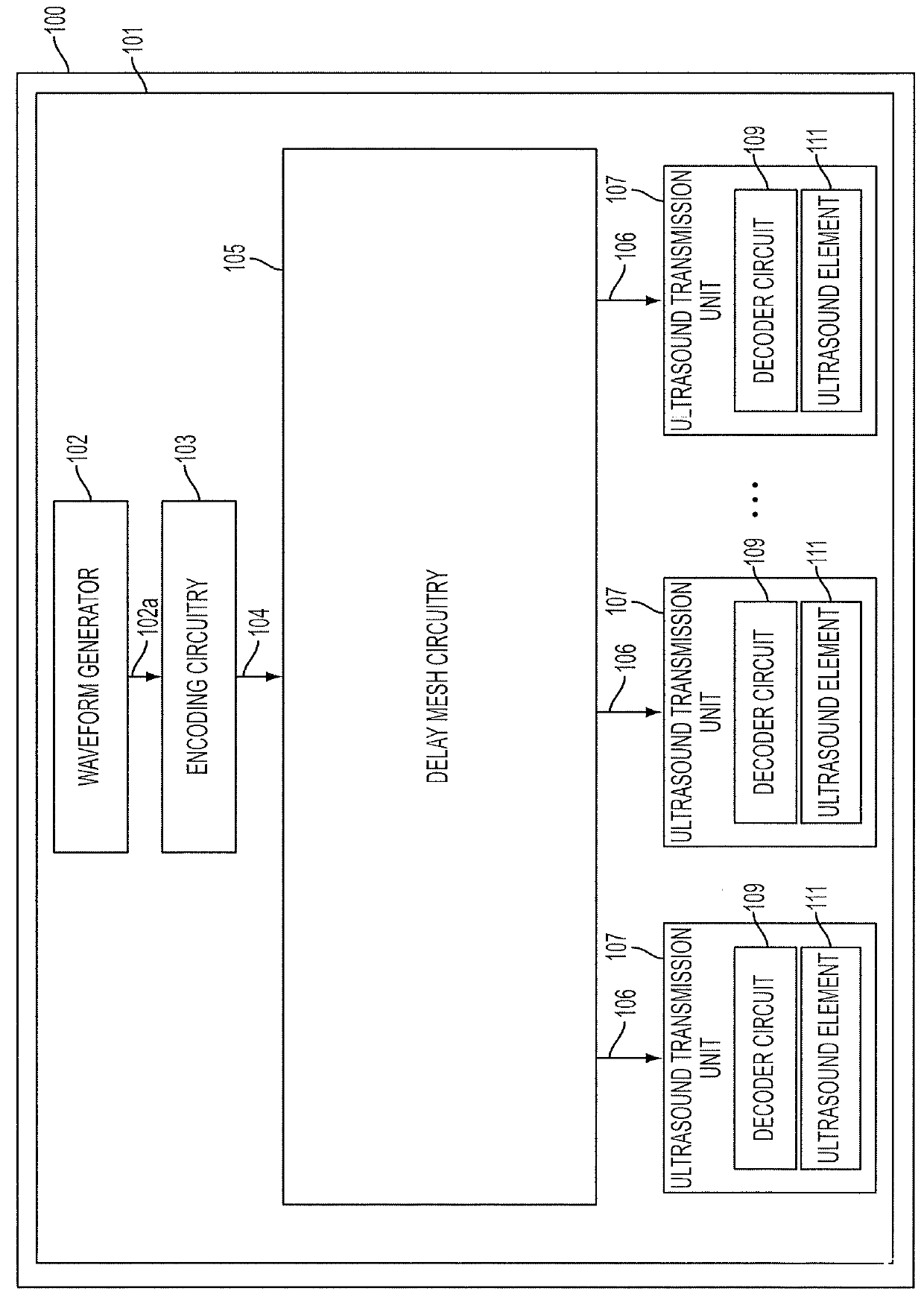
[0026]Aspects of the technology described herein relate to an ultrasound device circuitry architecture, as may form part of a single substrate ultrasound device having integrated ultrasonic transducers, for example complementary metal oxide semiconductor (CMOS) ultrasonic transducers. Thus, the circuitry architecture may in some embodiments form part of an ultrasound system-on-a-chip (SoC) having integrated circuitry and ultrasonic transducers integrated with (e.g., formed in, or monolithically integrated with) a substrate, such as a semiconductor substrate.

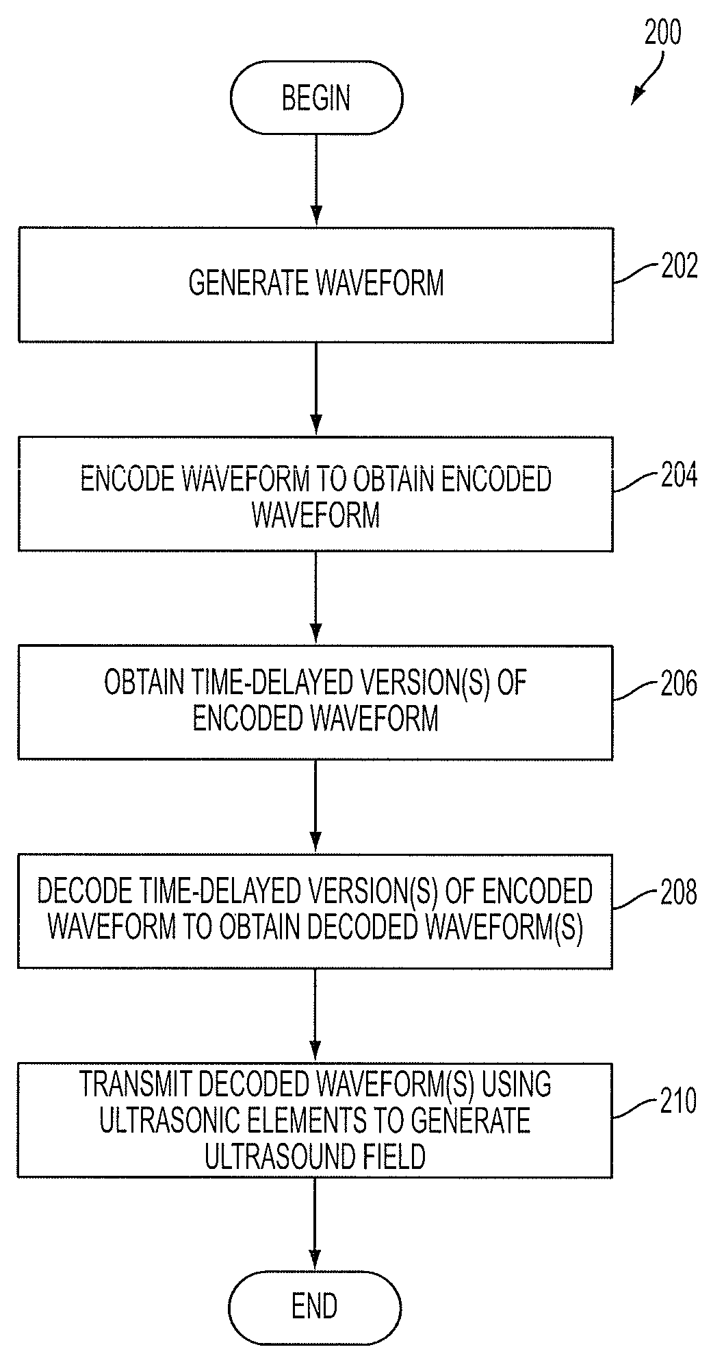
[0027]As described further below, aspects of the present technology provide delay and encoding / decoding circuitry configurations facilitating the generation of medically relevant ultrasound waveforms using an integrated ultrasonic transducer arrangement in a manner that is power- and data-efficient.

[0028]Applicants have appreciated that implementing an ultrasound device having integrated ultrasonic transducers and integrated circ...


PUM


Abstract

Aspects of the technology described herein relate to ultrasound device circuitry as may form part of a single substrate ultrasound device having integrated ultrasonic transducers. The ultrasound device circuitry may facilitate the generation of ultrasound waveforms in a manner that is power- and data-efficient.

Description

CROSS-REFERENCE TO RELATED APPLICATIONS[0001]The present application claims the benefit under 35 U.S.C. §119(e) of U.S. Provisional Patent Application Ser. No. 61 / 981,469 entitled “ARCHITECTURE OF SINGLE SUBSTRATE ULTRASONIC IMAGING DEVICES, RELATED APPARATUSES, AND METHODS,” filed Apr. 18, 2014, which is incorporated herein by reference in its entirety.FIELD[0002]Aspects of the technology described herein relate to the architecture of single substrate ultrasonic imaging devices, related apparatuses, and methods.BACKGROUND[0003]Conventional ultrasonic scanners dominating the ultrasound imaging industry have discrete transducers and control electronics. The transducers are often piezoelectric. As a result, the scanners are made using “dice and fill” manufacturing processes in which individual piezoelectric elements are cut and then positioned individually on a substrate to form a transducer probe. Such processes are prone to the cost, non-uniformity, and non-scalability of machining ...

Claims


Application Information

Patent Timeline
Patent Type & Authority Patents(United States)
IPC IPC(8): G10K11/00G10K11/34H03K5/13G01S7/52B06B1/06H03K5/00
CPCG01S7/52017G10K11/346H03K5/13B06B1/0607G01S7/5202H03K2005/00019G01S7/52019G01S7/52096G01S7/52034G01S15/8963G01S15/8993G01S15/8918G01S15/8925H03K2005/0015B06B1/0292
Inventor ROTHBERG, JONATHAN M.RALSTON, TYLER S.SANCHEZ, NEVADA J.CASPER, ANDREW J.
Owner BFLY OPERATIONS INC
Why Eureka
Try Eureka