
Parking lock control device for vehicle and control method

a technology for controlling devices and vehicles, applied in the direction of brake action initiation, vehicle components, braking element arrangements, etc., can solve problems such as increasing power consumption, and achieve the effect of suppressing power consumption and prolonging travel distan

Inactive Publication Date: 2016-01-12
NISSAN MOTOR CO LTD
View PDF21 Cites 1 Cited by
  • Summary
  • Abstract
  • Description
  • Claims
  • Application Information

AI Technical Summary

Benefits of technology

[0005]An object of the present invention is to provide a parking lock control device for the vehicle, which is capable of suppressing the power consumption.
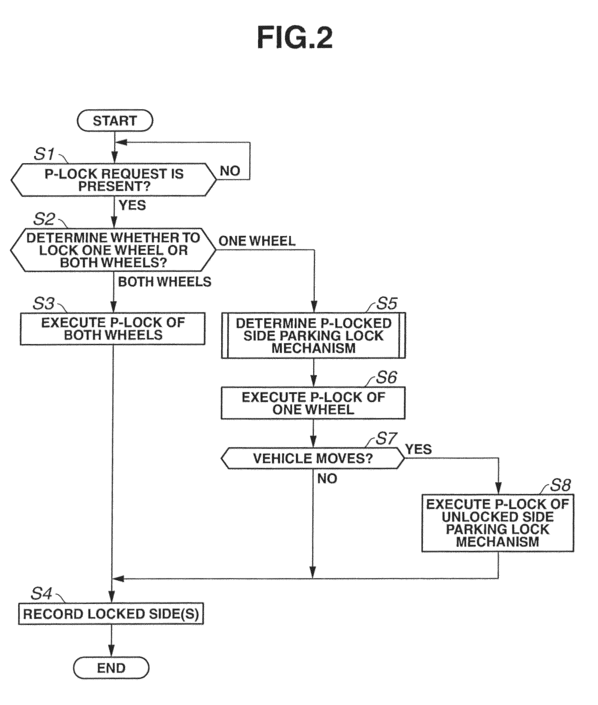
[0007]Accordingly, especially in a case where the vehicle does not move, by activating only one parking lock mechanism, the power consumption can be suppressed, and a travel distance can be made longer. Further, in a state in which only the first parking lock mechanism is activated, when the vehicle moves or when there is a possibility that the vehicle will move, the second parking lock mechanism that is provided at a different driving wheel from a driving wheel of the first parking lock mechanism is further activated. Therefore, the vehicle movement can be suppressed under all conditions.

Problems solved by technology

However, in a case where a plurality of parking lock mechanisms are activated, there arises a problem that increases power consumption.

Method used


Image

  • Parking lock control device for vehicle and control method
  • Parking lock control device for vehicle and control method
  • Parking lock control device for vehicle and control method

Examples


Embodiment Construction

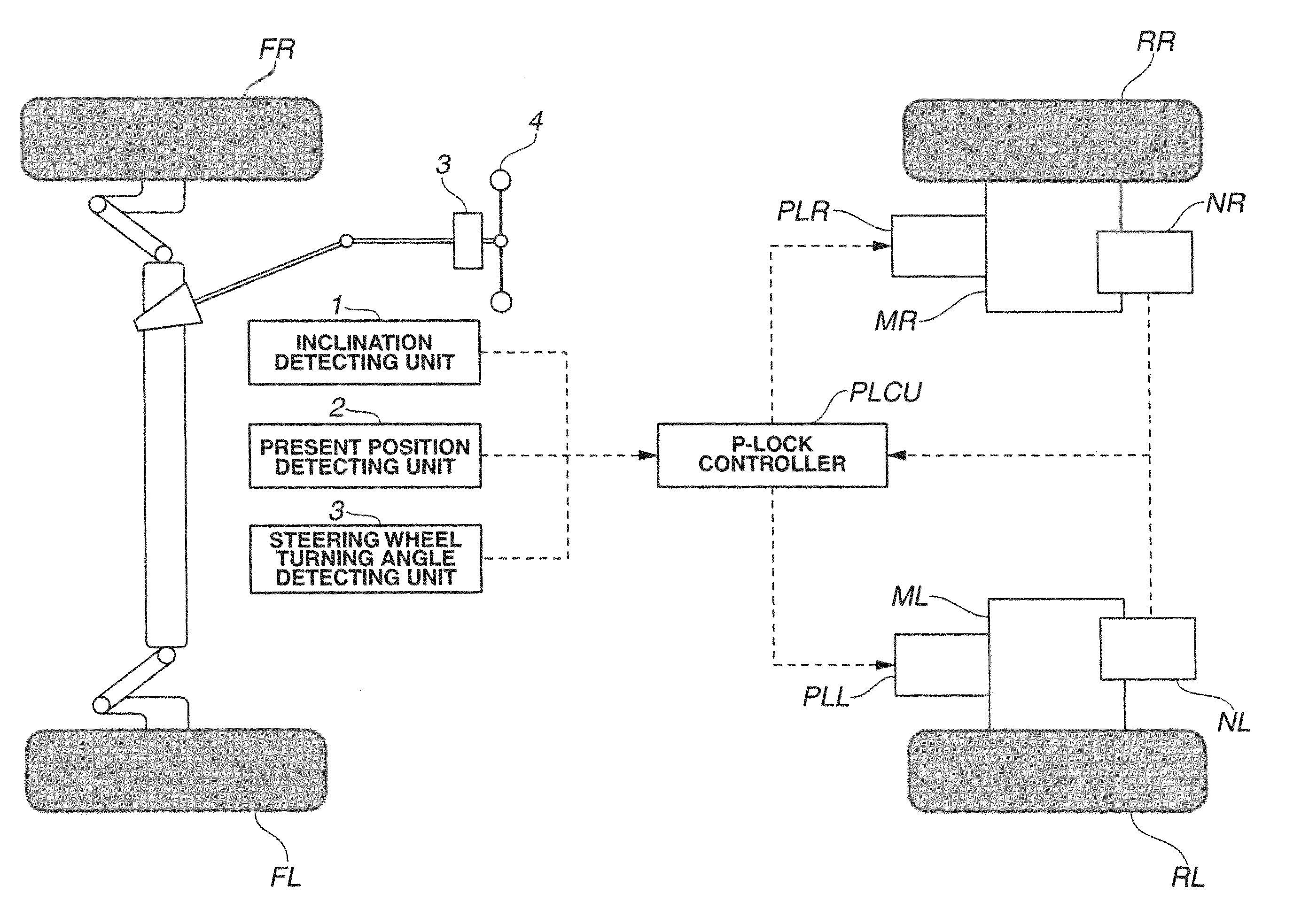
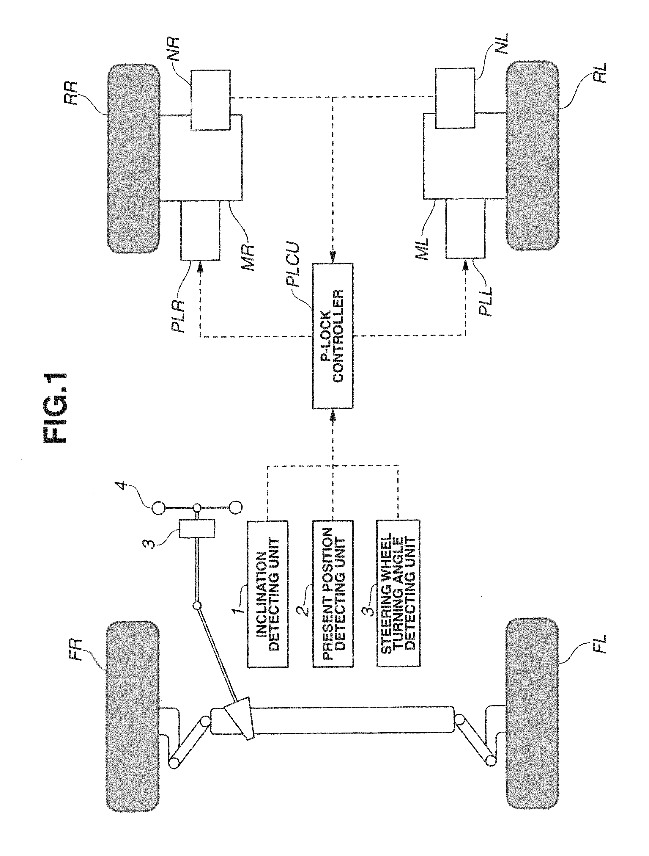
[0017]FIG. 1 is a general system diagram of a vehicle that is provided with a parking lock control device of an embodiment of the preset invention. The vehicle of the present embodiment is a rear wheel drive type electric vehicle, and has front wheels FR, FL that are driven wheels and rear wheels RR, RL that are driving wheels.

[0018]The rear wheel RR on a right side of the vehicle is provided with an in-wheel type drive motor MR (a right side motor) that directly drives this rear wheel RR, a parking lock mechanism PLR that can stop an rotation axis of the drive motor MR by connecting the rotation axis of the drive motor MR to a vehicle body side and a resolver NR (a vehicle behavior detecting unit) that detects a rotation speed (or a rotation angle) of the drive motor MR. Likewise, the rear wheel RL on a left side of the vehicle is provided with an in-wheel type drive motor ML (a left side motor) that directly drives this rear wheel RL, a parking lock mechanism PLL that can stop an ...


PUM


Abstract

In order to suppress power consumption, in a parking lock control device of a vehicle of the present invention, when a parking lock activation command is outputted, either one of right or left parking lock mechanism is activated. When it is estimated or detected that the vehicle moves in a state in which only the one parking lock mechanism is activated, the other parking lock mechanism is activated.

Description

TECHNICAL FIELD[0001]The present invention relates to a parking lock control device that locks a wheel.BACKGROUND ART[0002]A related art of a Patent Document 1 has disclosed a configuration in which, in a vehicle having a motor for each wheel, a parking lock mechanism is provided at each wheel, and when a parking lock request is outputted, by activating the parking lock mechanism of each wheel, the wheel is locked.[0003]However, in a case where a plurality of parking lock mechanisms are activated, there arises a problem that increases power consumption.CITATION LISTPatent Document[0004]Patent Document 1: Japanese Patent Provisional Publication Tokkai No. 2007-314036SUMMARY OF THE INVENTION[0005]An object of the present invention is to provide a parking lock control device for the vehicle, which is capable of suppressing the power consumption.[0006]In the parking lock control device for the vehicle of the present invention, when a parking lock activation command is outputted, a first...

Claims


Application Information

Patent Timeline
Patent Type & Authority Patents(United States)
IPC IPC(8): B60T8/172B60T1/00B60T7/12
CPCB60T8/172B60T1/005B60T7/122
Inventor HASEGAWA, JUNICHIYAMAUCHI, YASUHIRO
Owner NISSAN MOTOR CO LTD
Learn More