Asymmetric area lighting lens

a technology of asymmetric lighting and lens, applied in the field of optical lens devices, lighting systems, asymmetrically distributing light, can solve the problems of reducing lighting efficiency, uneven light distribution profiles, and often inadequate reflectors for many asymmetric lighting applications, and achieve the effect of efficient projection into a specified region

Inactive Publication Date: 2016-01-12
UNIVERSAL LIGHTING TECHNOLOGIES
View PDF15 Cites 8 Cited by
  • Summary
  • Abstract
  • Description
  • Claims
  • Application Information

AI Technical Summary

Benefits of technology

[0016]Another object of the present invention is to provide a wide area light distribution from a light source, such as a light emitting diode (LED), to provide a uniform lit area with efficient projection into a specified region.
[0020]Yet another object of the present invention is to provide an optical lens that can be manufactured in a straight-pull injection molding tooling system.

Problems solved by technology

However, reflectors are often inadequate for many asymmetric lighting applications because they absorb photons and reduce lighting efficiency.
Additionally, reflectors may become hot during use or may become damaged or misaligned, resulting in uneven light distribution profiles.
Reflectors also may be expensive to produce and align in a mass production environment.
One problem with conventional asymmetric lens devices is the use of primarily refractive exterior surfaces for distributing light asymmetrically.
Additionally, conventional asymmetric lens devices do not achieve optimal efficiency and do not minimize unwanted light emission toward the desired dark regions.

Method used


Image

  • Asymmetric area lighting lens
  • Asymmetric area lighting lens
  • Asymmetric area lighting lens

Examples


Embodiment Construction

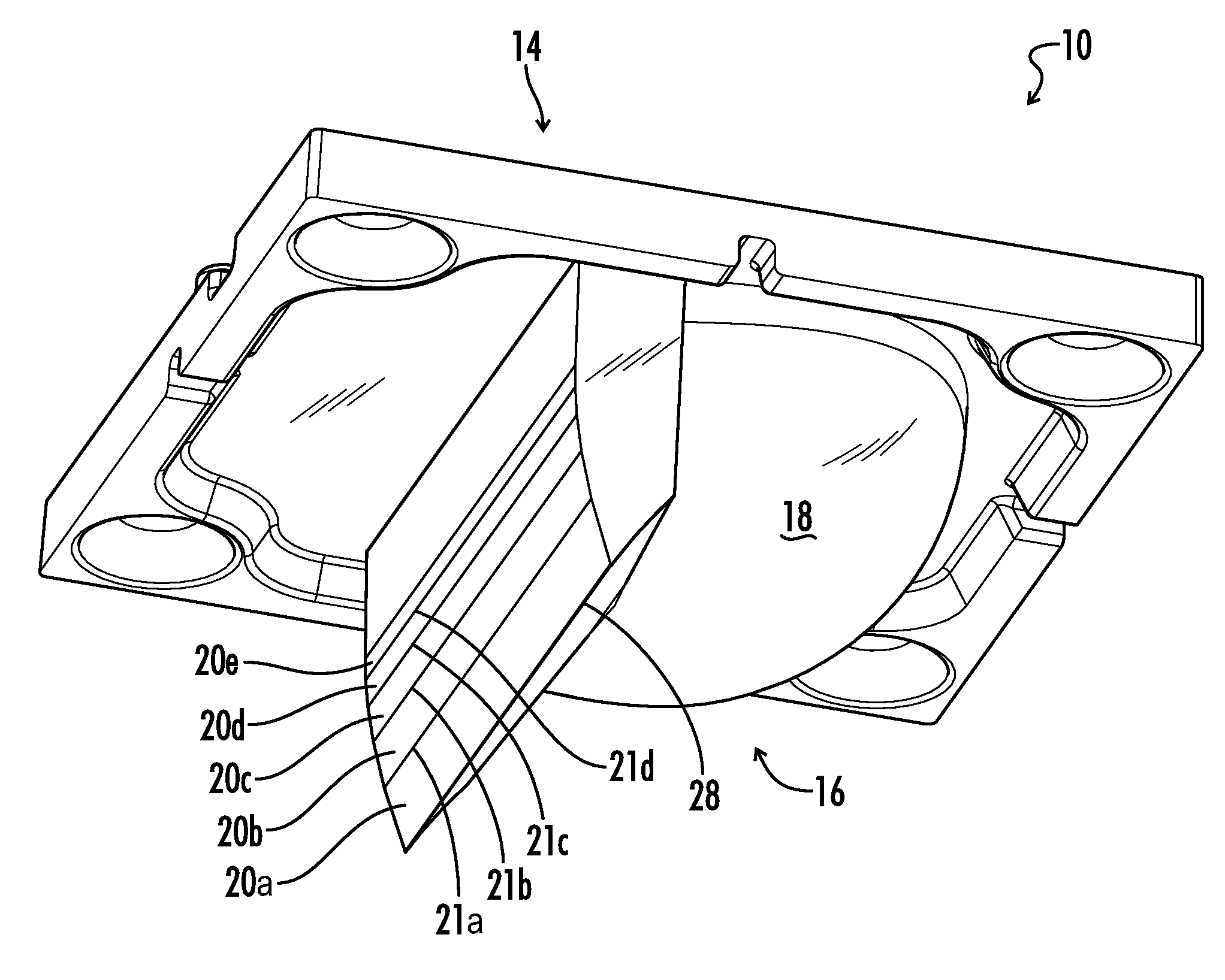
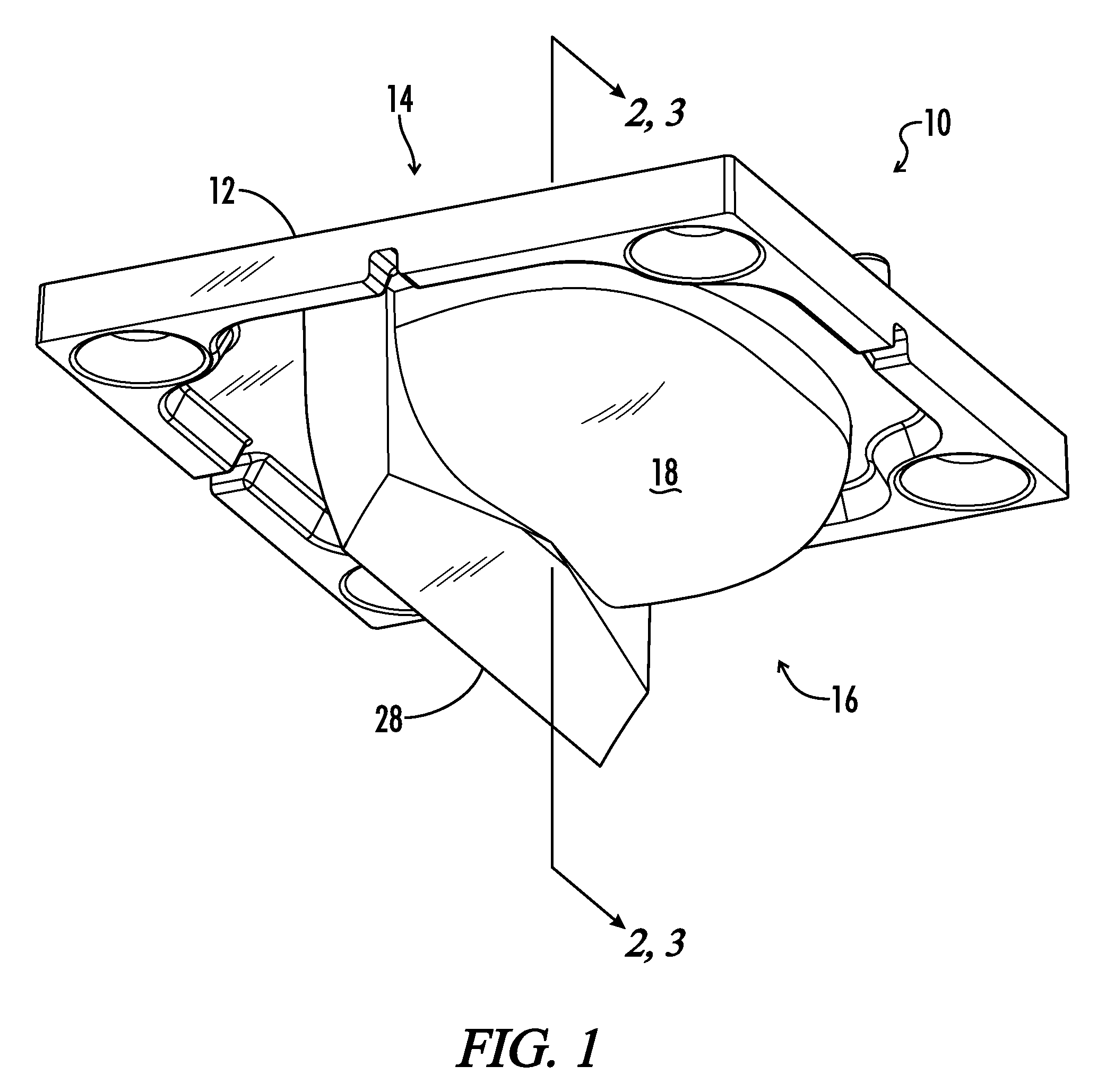
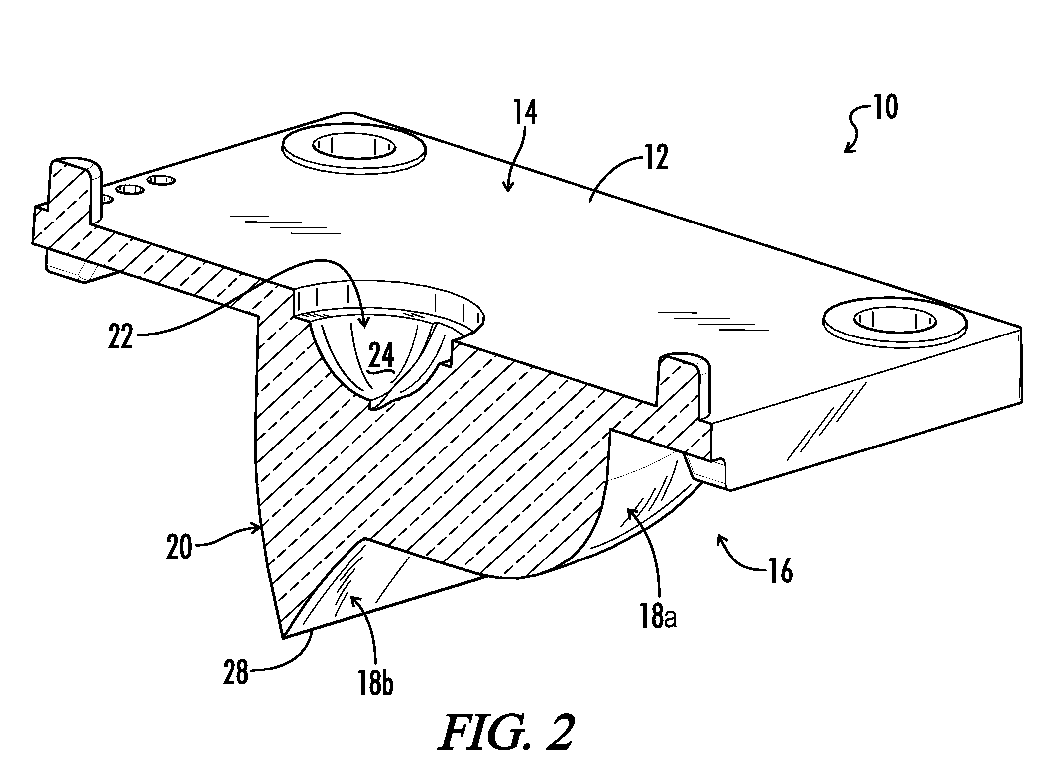
[0031]Referring now to the drawings, FIG. 1 illustrates an embodiment of an optical lens apparatus for asymmetrically distributing light in an area. The lens apparatus is generally configured to be positioned on or near a light emitter such as a lamp, bulb, light emitting diode (LED) or other suitable light emitter. The lens apparatus includes a lens body 10 having an input side 14 and an output side 16. The input side 14 includes the side where the light source is placed. In some embodiments, an emitter recess 22 is defined on the input side 14 of lens body 10. Emitter recess 22 provides a region for placement of a light emitter such as an LED package, a lamp or a bulb. In alternative embodiments, a light emitter may be placed against or near input side 14 without any emitter recess 22 present.

[0032]Lens body 10 may be used with a light emitter in various applications, such as overhead lighting, street lighting, vehicle lighting, indoor lighting, outdoor lighting, or other lighting...


PUM


Abstract

A lens for distributing light from a light emitter in a desired asymmetric illumination profile includes a lens body having an input side and an output side. The input side receives light from an emitter, and the output side includes a major total internal reflection surface and a refractive surface. A primary emission axis associated with the emitter is defined through the lens body, and a transverse reference plane is positioned parallel to the primary emission axis. A desired illumination region is located on a first side of the reference plane, and a desired dark region is located on a second side of the reference plane. In some embodiments, the total internal reflection surface is entirely positioned on the second side of the reference plane. In additional embodiments, the total internal reflection surface includes a plurality of substantially planar adjacent longitudinal faces.

Description

CROSS-REFERENCE TO RELATED APPLICATION[0001]This application claims benefit of U.S. Provisional Patent Application Ser. No. 61 / 659,828 filed Jun. 14, 2012 entitled Asymmetric Area Lighting Lens with Improved Uniformity, which is hereby incorporated by reference in its entirety.[0002]A portion of the disclosure of this patent document contains material that is subject to copyright protection. The copyright owner has no objection to the reproduction of the patent document or the patent disclosure, as it appears in the U.S. Patent and Trademark Office patent file or records, but otherwise reserves all copyright rights whatsoever.STATEMENT REGARDING FEDERALLY SPONSORED RESEARCH OR DEVELOPMENT[0003]Not Applicable.REFERENCE TO SEQUENCE LISTING OR COMPUTER PROGRAM LISTING APPENDIX[0004]Not Applicable.BACKGROUND OF THE INVENTION[0005]The present invention relates generally to lighting products and more particularly to optical lens devices, lighting systems, and associated methods for asymme...

Claims


Application Information

Patent Timeline
Patent Type & Authority Patents(United States)
IPC IPC(8): F21V5/00F21K99/00F21V13/04F21V7/00F21V5/04H01L33/54H01L33/60G02B3/02
CPCF21V13/04F21K9/50F21V5/04F21V7/0091H01L33/54H01L33/60F21Y2101/02G02B3/02F21Y2115/10
Inventor DIEKER, HENNINGHOUSEHOLDER, JOHN R.
Owner UNIVERSAL LIGHTING TECHNOLOGIES
Why Eureka
Try Eureka