Infrared radiant emitter

a technology of radiant emitter and infrared light, which is applied in the direction of heating types, lighting and heating apparatus, and domestic stoves or ranges. it can solve the problems of wasting at least 40% of energy output, wasting approximately 40 watts of heating ceramic glass, and achieving the effect of improving the rate and efficiency of heating the thermal target, efficient radiant energy projection, and high efficiency

Active Publication Date: 2020-10-29
MASTEN JR JAMES WILLIAM
View PDF0 Cites 0 Cited by
  • Summary
  • Abstract
  • Description
  • Claims
  • Application Information

AI Technical Summary

Benefits of technology

This patent describes a method and device for efficiently transmitting heat through ceramic glass using infrared light. The device is a low-cost, infrared light source that can be easily installed and managed to prevent damage to the ceramic glass. The method uses a natural beam pattern to maximize the amount of heat transmitted through the glass while minimizing the heating of the ceramic surface. Overall, this technology enhances the speed and efficiency of heating while reducing waste.

Problems solved by technology

Still, heating efficiencies were very low and many efforts were made to limit the energy lost by the (resistive) element.
This means that at the very best, radiant elements that operate in this lower passband are wasting at least 40% of their energy output as ineffective localized heating.
What is worse is that for every 100 Watts of radiant energy directed at the ceramic glass, approximately 40 Watts will be lost to heating the ceramic glass.
Additionally, all “temperature” sensors measure “intensity” and not “power,” and as such they cannot differentiate between reflected, transmitted or radiated energy.
Thus optical sensors can be confused by their inability to quantify observed “power” and these sensors always find the highest temperature in their field of view, which could be a reflection of the radiant source.
An apparatus such as that disclosed in U.S. Pat. No. 6,111,228, using waveguides to “look” at the ceramic glass and duct radiant energy to an optical sensor, is unlikely to yield a reliable measure of the ceramic glass, because the higher temperature of the radiant source could be transmitted through the glass to the waveguide or reflected from the glass to the waveguide, dominating (by the fourth power of the difference) the lower-temperature radiant energy of the cooler ceramic glass plate.
As defined by the Stefan-Boltzmann law, the elements of equal temperatures will not effectively transmit energy to each other, but they will dramatically heat the air between them.

Method used


Image

  • Infrared radiant emitter
  • Infrared radiant emitter
  • Infrared radiant emitter

Examples


Embodiment Construction

[0089]The following detailed description of a preferred embodiment of the present invention proceeds with reference to the delivery of thermal energy to a cooking utensil sitting on top of a second generation ceramic glass plate as provided by either of the two major manufacturers after the mid-1990s.

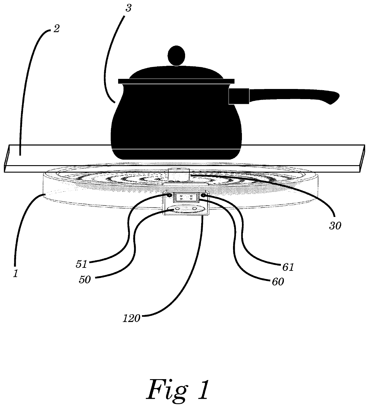
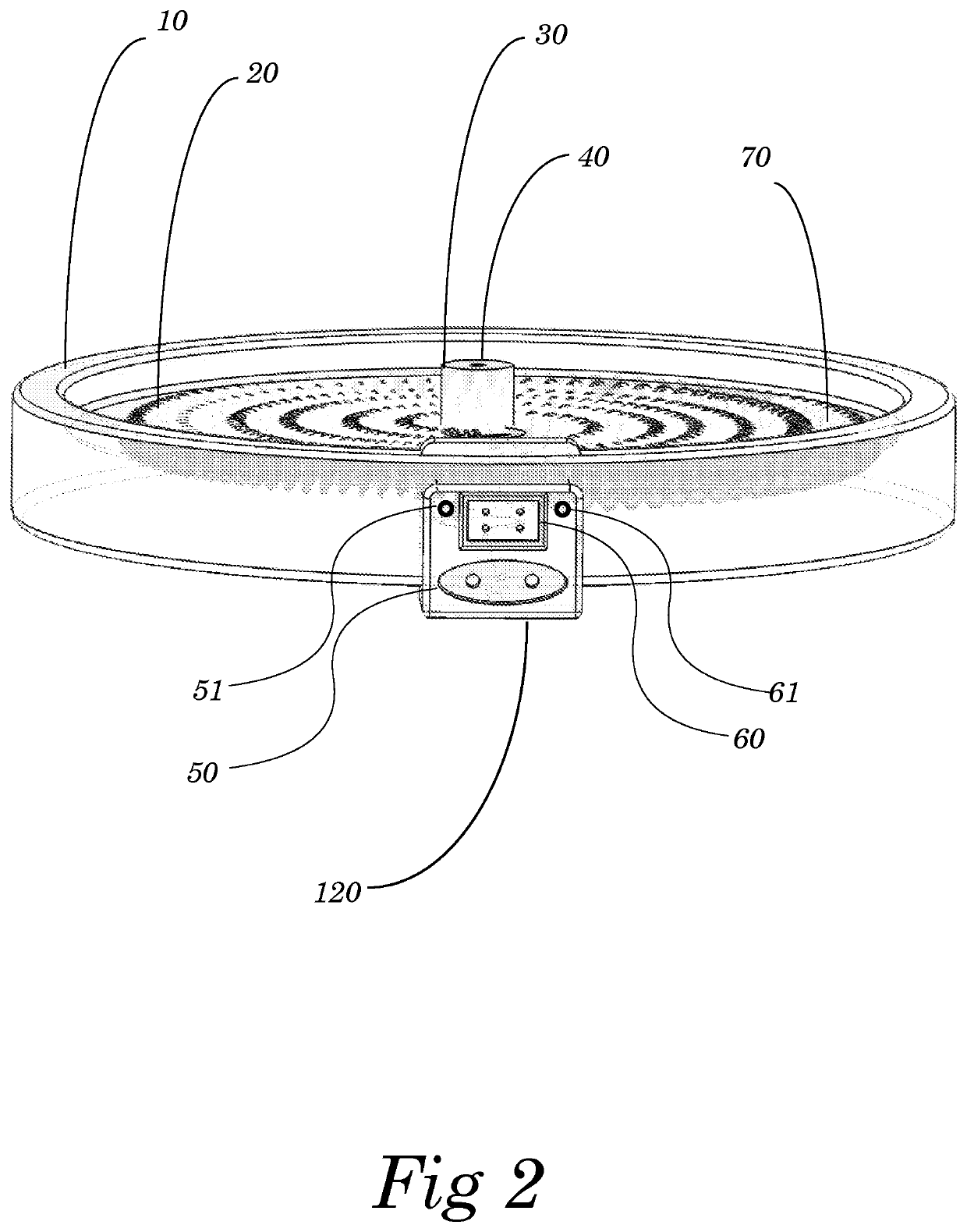
[0090]The following description of the present invention is in the context of a preferred embodiment comprising a radiant emitter heating element 1, smooth top ceramic glass cooktop 2, and utilizing a common cooking utensil 3. The combined system is intended to be heated by a uniquely configured radiant emitter element 1 optimized to deliver radiant energy through the ceramic glass 2 to the cooking utensil 3 sitting on top of the ceramic glass.

[0091]The basic apparatus disclosed herein is not intended to be limited to smooth top cooktop configurations, and in fact could be used to source the precise control of thermal energy from a (resistive) radiant emitter in a different configuratio...


PUM

PropertyMeasurementUnit
temperatureaaaaaaaaaa
temperaturesaaaaaaaaaa

Abstract

An infrared heating apparatus includes a sheet of ceramic glass having a passband in the infrared spectrum, a metal resistive element having a first portion that is covered by a ceramic refractory material and a second portion that is exposed by the ceramic refractory material, and a controller that controls the metal resistive element to emit infrared radiation in a wavelength corresponding to the passband of the ceramic glass.

Description

CROSS REFERENCE TO RELATED APPLICATIONS[0001]The present application is a continuation of U.S. patent application Ser. No. 15 / 439,902, filed Feb. 22, 2017, and issued as U.S. Pat. No. 10,718,527 on Jul. 21, 2020, which claims the benefit of Provisional Application No. 62 / 372,540, filed Aug. 9, 2016, the disclosures of which are incorporated in their entirety herein by reference.FIELD OF THE INVENTION[0002]The present invention reveals significant improvements to the method and apparatus for the heating of an object through a smooth ceramic glass surface.BACKGROUND OF THE INVENTION[0003]Since the development of various ceramic glasses in the 1960's and 1970's, the fundamental feature of extremely low coefficient of expansion has created the opportunity for smooth-top cooking surfaces with heating sources beneath the ceramic glass. Smooth-top cooking surfaces were attractive and practical because they were easy to clean.[0004]Initially, the utilization of conduction heating of the cer...

Claims


Application Information

Patent Timeline
Patent Type & Authority Applications(United States)
IPC IPC(8): F24C7/08H05B3/74F24C15/10H05B1/02
CPCH05B2213/07F24C7/046F24C15/102H05B3/748H05B1/0266F24C7/087H05B1/02
Inventor MASTEN, JR., JAMES WILLIAM
Owner MASTEN JR JAMES WILLIAM
Why Eureka
Try Eureka