Error correction circuit for data communication providing parallelizable linear programming decoding

a technology of error correction circuit and data communication, applied in the direction of coding, code conversion, instruments, etc., can solve the problems of inability to guarantee the convergence of a set of bits that meets the constraint of parity rules, inability to assume errors in transmission or storage, and inability to decode information encoded using low density parity check codes. achieve the effect of improving execution speed and improving scalability with long data words

Active Publication Date: 2014-12-30
WISCONSIN ALUMNI RES FOUND
View PDF17 Cites 0 Cited by
  • Summary
  • Abstract
  • Description
  • Claims
  • Application Information

AI Technical Summary

Benefits of technology

[0011]It is thus a feature of at least one embodiment of the invention to provide a robust error correction and detection decoding that can be proven to converge. Current belief propagation is not subject to this rigorous understanding. It is further a feature of at least one embodiment of the invention to provide an error correction and detection system that does not appear to be subject to an error floor, making it suitable for extremely high reliability error detection and correction.
[0013]It is thus a feature of at least one embodiment of the invention to provide a decoding system that reduces data flow paths by modification of replicas, thus offering potential for simpler hardware implementation.
[0015]It is thus a feature of at least one embodiment of the invention to permit parallel processing of the modifications of the replicas for improved scalability with long data words and improved execution speed.
[0018]The electronic circuit may provide multiple independently executing computational elements associated with different values of the corrected string of bits to substantially simultaneously adjust the different values of the corrected string of bits.
[0021]It is thus a feature of at least one embodiment of the invention to provide a mechanism for efficiently projecting solutions to the parity polytope, the latter representing a relaxation to the decoding process permitting linear programming to be applied.
[0025]It is thus a feature of at least one embodiment of the invention to provide a simple and widely applicable model for the transmission link.

Problems solved by technology

A naïve redundancy scheme may simply duplicate the transmission or storage of the data; however, sophisticated redundancy systems provide a limited number of detection and correction bits (henceforth “check bits”) each of which serve to detect and / or correct errors in multiple other data bits.
If not, an error in transmission or storage can be assumed.
Decoding information that has been encoded using low density parity check codes is computationally demanding, involving the determination of a most likely transmitted string in the face of errors and subject to the overlapping constraints of the originally transmitted message.
Unfortunately, although belief propagation is often empirically successful, there is no guarantee that it will converge to a set of bits that meets the constraint of the parity rules.
Further, belief propagation is subject to an “error floor” representing a limit to its ability to detect and correct errors.

Method used


Image

  • Error correction circuit for data communication providing parallelizable linear programming decoding
  • Error correction circuit for data communication providing parallelizable linear programming decoding
  • Error correction circuit for data communication providing parallelizable linear programming decoding

Examples


Embodiment Construction

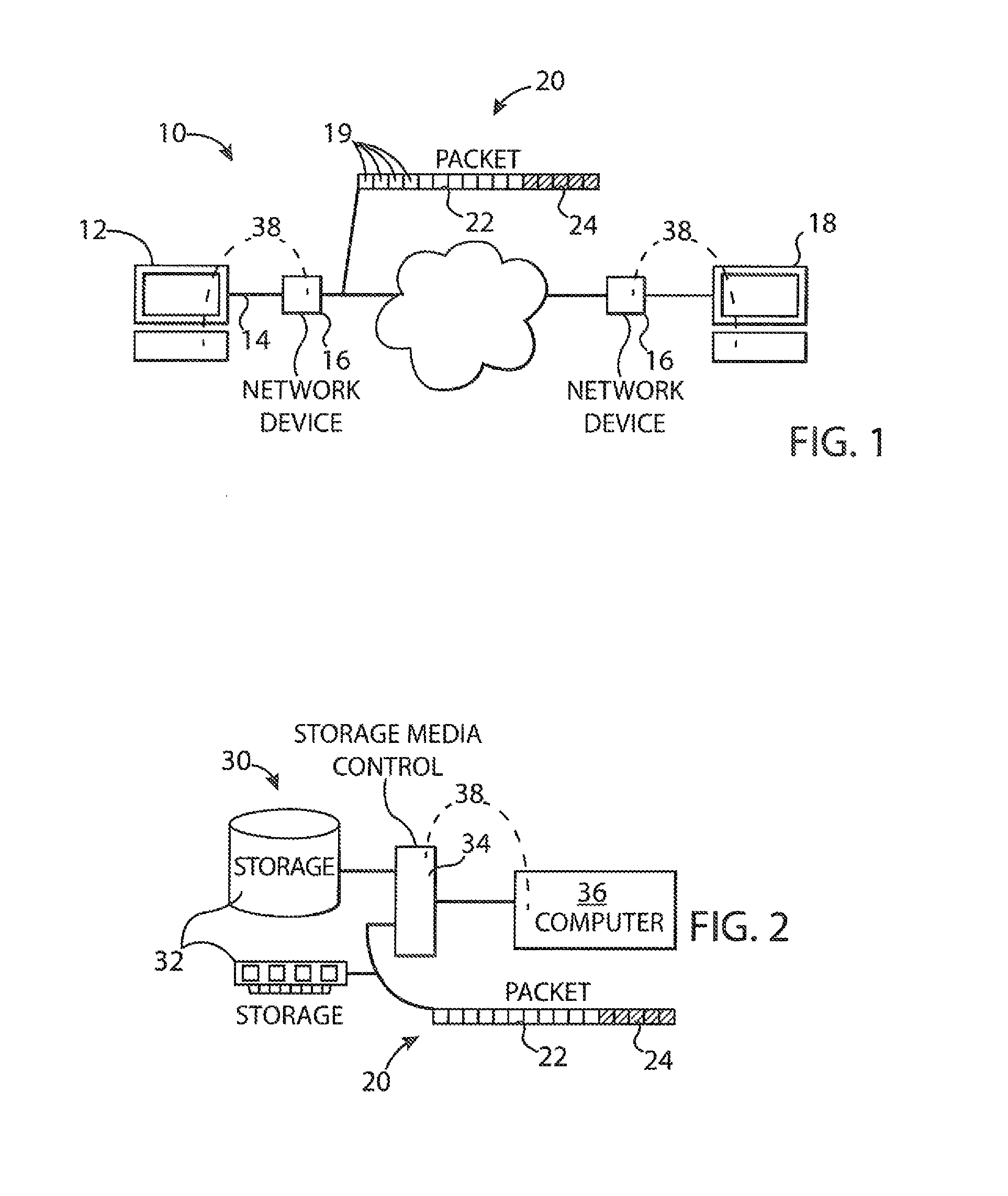
[0039]Referring now to FIG. 1, a data communication system 10 may provide for a first terminal device 12, for example a computer terminal or server, communicating with network media 14, for example, the latter being copper conductors, optical media, or radio communication or the like. The network media 14 communicates through one or more network devices 16, such as routers or other switches, with a second terminal device 18 similar to the first terminal device 12.

[0040]Data communicated on the data communication system 10 may comprise data composed of string of binary bits, termed a “packet”20, including a content portion 22 and error correcting portion 24 which may be segregated as shown or interleaved arbitrarily. The error correcting portion 24 provides message redundancy to improve one or both of error detection and error correction in the event that bits of the packet 20 are corrupted or flipped, being generally changing a bit value from 1 to 0 or 0 to 1.

[0041]Referring now als...


PUM


Abstract

An error detection / correction system provides an electronic circuit detecting and correcting transmission errors using linear programming. Linear programming techniques are made practical for real-time error correction and decoding by dividing the linear programming problem into independent parallelizable problems so that separate independent portions of the electronic circuit may simultaneously address solutions related to individual bits and / or parity rules.

Description

BACKGROUND OF THE INVENTION[0001]The present invention relates to error correction circuits for detecting and correcting errors in transmitted or stored digital data and in particular to an error correction circuit providing high-speed linear programming detection and error correction.[0002]The reliable transmission and storage of digital data, for example binary symbols transmitted as electrical impulses over data communication networks or stored on digital storage media, may employ error detection and / or correction circuitry and protocols to guard the transmitted or stored data against corruption.[0003]Generally, error detection and correction is obtained by providing redundant bits in the transmitted or stored data. A naïve redundancy scheme may simply duplicate the transmission or storage of the data; however, sophisticated redundancy systems provide a limited number of detection and correction bits (henceforth “check bits”) each of which serve to detect and / or correct errors in...

Claims


Application Information

Patent Timeline
Patent Type & Authority Patents(United States)
IPC IPC(8): H03M13/00G11C29/00G06F11/10
CPCH03M13/6393H04L1/0045G06F11/10G06F11/104
Inventor DRAPER, STARKRECHT, BENJAMINBARMAN, SIDDHARTH
Owner WISCONSIN ALUMNI RES FOUND
Why Eureka
Try Eureka