Torque sensor

a technology of torque sensor and magnetic shield, which is applied in the direction of force/torque/work measurement apparatus, instruments, measurement devices, etc., can solve the problem that the magnetic sensor produces an error in detection value, and achieve the effect of simplifying the configuration of the magnetic shield and making the installation of the magnetic shield easy

Inactive Publication Date: 2006-05-30
DENSO CORP +1
View PDF19 Cites 42 Cited by
  • Summary
  • Abstract
  • Description
  • Claims
  • Application Information

AI Technical Summary

Benefits of technology

[0009]The magnetic sensor detects the density of magnetic flux generated in the air gap of the opposed flux collecting rings. When the flux collecting rings are influenced by the external magnetic field, the magnetic sensor produces an error in detection value. Accordingly, covering the outer cylindrical surface of the set of flux collecting rings makes it possible to effectively eliminate the adverse influence given by the magnetic fields produced by external magnetic members including car speakers.
[0010]Furthermore, the magnetic shield does not cover all of the magnetic circuit of the torque sensor. The magnetic shield covers only the outer cylindrical surface of the set of flux collecting rings. The configuration of the magnetic shield can be simplified. Installation of the magnetic shield becomes easy.
[0012]Providing the side portion to the magnetic shield is effective to eliminate the adverse influence given by the magnetic fields produced by external magnetic members including car speakers. The detection error of the magnetic sensor can be further reduced.
[0014]As the flux collecting rings are opposed to each other via the air gap, integrating the flux collecting rings together with the magnetic shield by resin molding makes it possible to simplify the installation. This magnetic shielding structure is preferably employable for mass production.
[0016]According to this arrangement, the magnetic shield does not cover all of the magnetic circuit of the torque sensor. The magnetic shield directly covers only the outer cylindrical surface of the set of flux collecting rings. The configuration of the magnetic shield can be simplified. Installation of the magnetic shield becomes easy.

Problems solved by technology

When the flux collecting rings are influenced by the external magnetic field, the magnetic sensor produces an error in detection value.

Method used


Image

  • Torque sensor
  • Torque sensor
  • Torque sensor

Examples


first embodiment

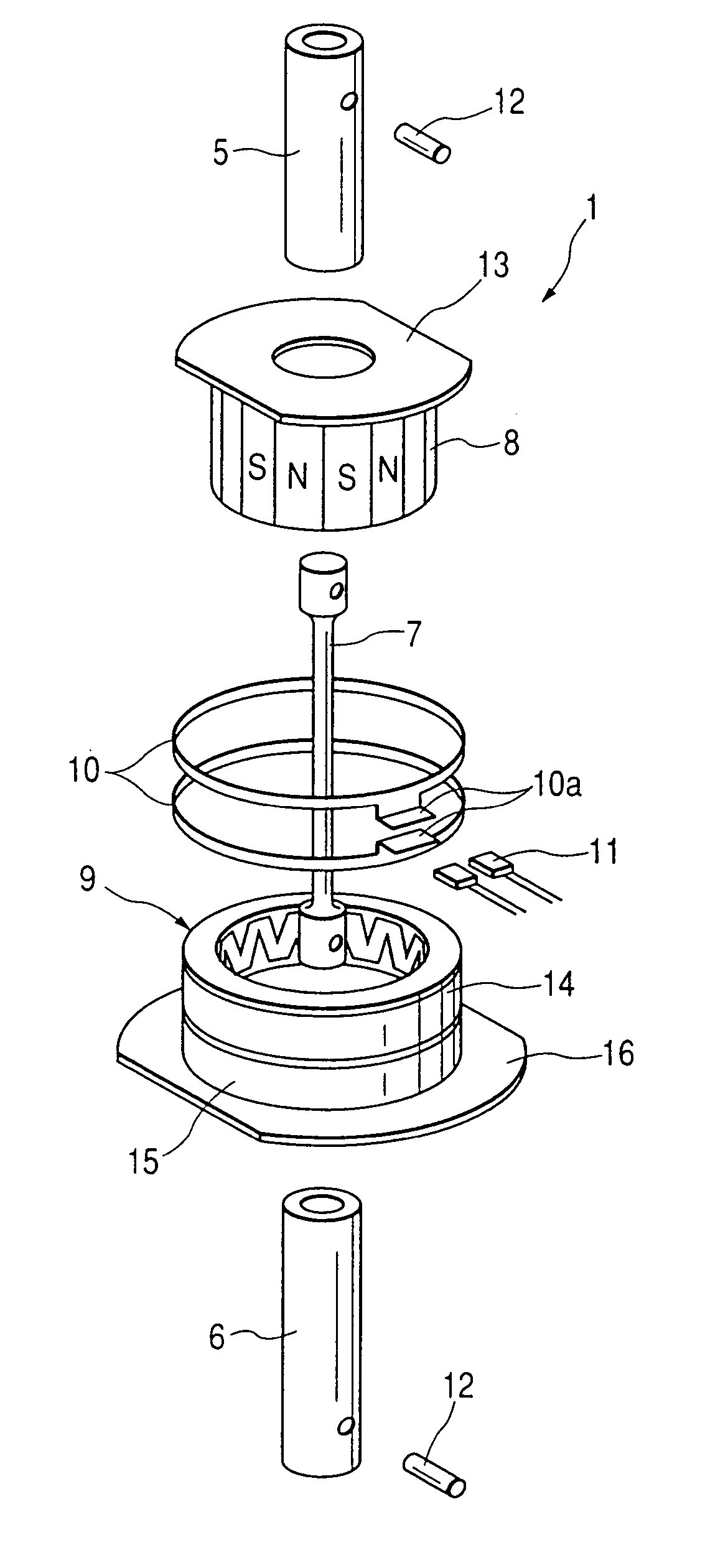
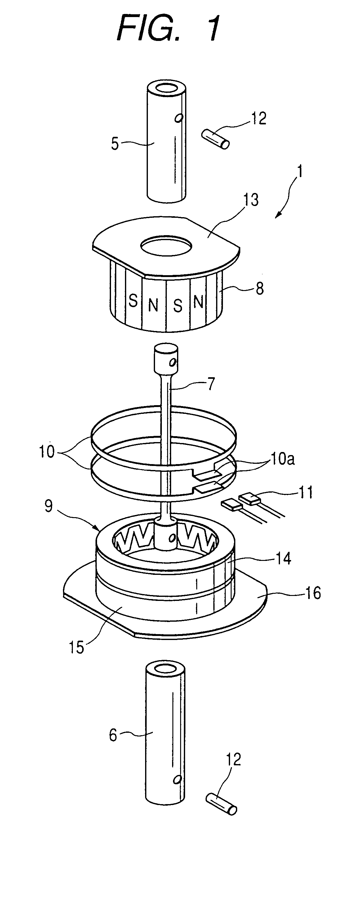
[0035]FIG. 1 is an exploded perspective view showing a torque sensor 1 in accordance with a preferred embodiment of the present invention. For example, the torque sensor 1 of this embodiment is used for a motor-driven power steering apparatus shown in FIG. 8. The torque sensor 1 detects a steering force (i.e., a shaft torque) of a steering wheel 2, and sends the detected steering force to an ECU (electronic control unit) 3. The ECU 3 controls the output of a motor-driven motor 4 in accordance with the steering force detected by the torque sensor 1.

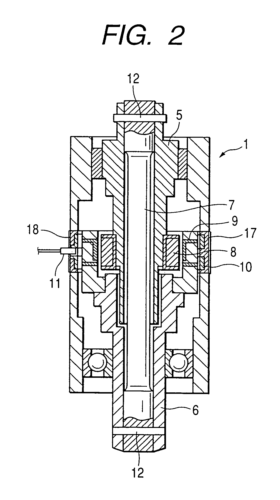
[0036]The torque sensor 1 is provided between an input shaft 5 and an output shaft 6 which cooperatively constitute a steering shaft. As shown in FIG. 1, the torque sensor 1 includes a torsion bar 7, a multipolar magnet 8, one set of magnetic yokes 9, one set of flux collecting rings 10, and a magnetic sensor 11.

[0037]As shown in FIG. 2, the torsion bar 7 is an elastic rod member having one end connected to the input shaft 5 via a pin 12 a...

second embodiment

[0053]FIG. 9 is a perspective view showing an assembly of one set of flux collecting rings 10 being integrated by resin molding and assembled with a magnetic shield 18 in accordance with another embodiment.

[0054]As shown in FIG. 10B, the magnetic shield 18 of this embodiment has side portions 18b at both ends in axial lateral direction so as to be configured as a whole into U shaped in cross section.

[0055]As shown in FIG. 9, the side portions 18b of magnetic shield 18 cover the side surfaces of the molding member 17. Thus, it becomes possible to greatly reduce the adverse influence given by the external magnetic field. The detection error of the magnetic sensor 11 can be further reduced.

modified embodiment

[0056]According to the first embodiment, the magnetic shield 18 is later fixed to the assembly of the set of flux collecting rings 10 after the resin molding operation is accomplished. It is however possible to integrate the set of flux collecting rings 10 and the magnetic shield 18 by resin molding. Integrating the set of flux collecting rings 10 and the magnetic shield 18 makes it possible to simplify the installation. This magnetic shielding structure is preferably employable for mass production. This modification is also applicable to the second embodiment.


PUM

PropertyMeasurementUnit
magneticaaaaaaaaaa
magnetic fieldaaaaaaaaaa
magnetic fluxesaaaaaaaaaa

Abstract

A first shaft and a second shaft are connected coaxially. A torsion bar converts a torque applied between two shafts into a torsion displacement. A multipolar magnet is fixed to the first shaft. One set of magnetic yokes is fixed to the second shaft and disposed in a magnetic field generated by the multipolar magnet. One set of flux collecting rings is disposed along an outer surface of the set of magnetic yokes and opposed to each other via an air gap in an axial direction. A magnetic sensor is provided for detecting the density of magnetic flux generated in the air gap. An outer cylindrical surface of the set of flux collecting rings is surrounded by a magnetic shield.

Description

CROSS REFERENCE TO RELATED APPLICATIONS[0001]This application is a continuation application of U.S. patent application Ser. No. 10 / 673,278, filed on Sep. 30, 2003, now U.S. Pat. No. 6,928,887, which is based on and incorporates herein by reference Japanese Patent Application No. 2002-293181 filed on Oct. 7,2002.BACKGROUND OF THE INVENTION[0002]This invention relates to a torque sensor detecting a shaft torque applied to a rotary shaft as change of magnetic flux density (i.e., strength of magnetic field).[0003]As a conventional technique, Japanese Patent Application Laid-open No. 2003-149062 (FIG. 15) discloses a torque sensor.[0004]This torque sensor is, for example, used for a motor-driven power steering apparatus. As shown in FIG. 11, an input shaft 100 and an output shaft 110 are coaxially connected by a torsion bar 120. A multipolar magnet 130 is fixed to the input shaft 100. One set of magnetic yokes 140, fixed to the output shaft 110, is disposed in a magnetic field generated ...

Claims


Application Information

Patent Timeline
Patent Type & Authority Patents(United States)
IPC IPC(8): G01L3/12G01L3/02G01L3/10G01L3/14G01L5/22
CPCG01L5/221G01L3/101G01L3/104
Inventor NAKANE, NAOKIFUKAYA, SHIGETOSHI
Owner DENSO CORP
Why Eureka
Try Eureka