Torque sensor

Active Publication Date: 2005-08-16
DENSO CORP +1
View PDF14 Cites 46 Cited by
  • Summary
  • Abstract
  • Description
  • Claims
  • Application Information

AI Technical Summary

Benefits of technology

[0015]According to this arrangement, the magnetic shield does not cover all of the magnetic circuit of the torque sensor. The magnetic shield directly covers only the ou

Problems solved by technology

When the flux collecting rings are influenced by the external magne

Method used


Image

  • Torque sensor
  • Torque sensor
  • Torque sensor

Examples


Example

First Embodiment

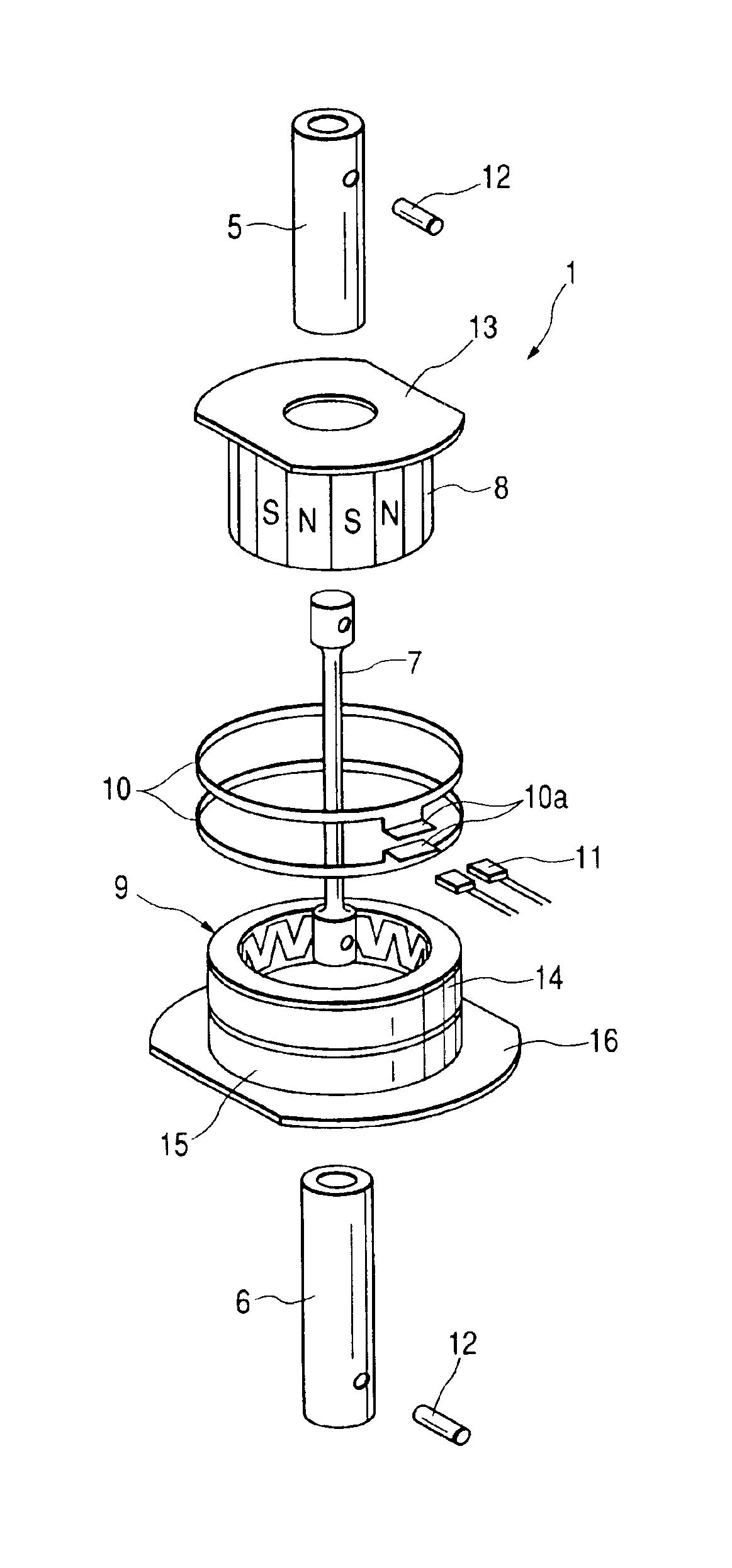
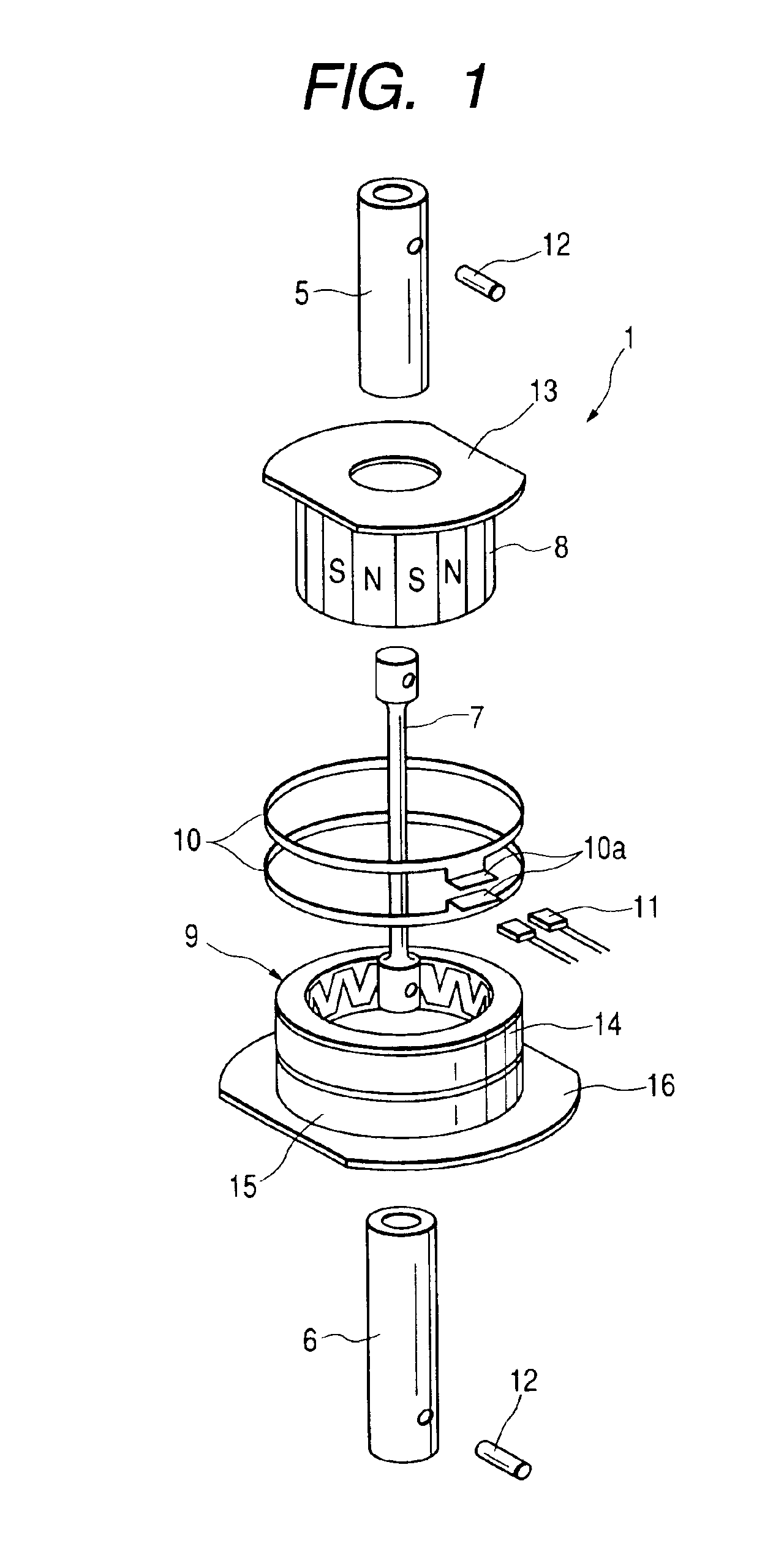
[0034]FIG. 1 is an exploded perspective view showing a torque sensor 1 in accordance with a preferred embodiment of the present invention. For example, the torque sensor 1 of this embodiment is used for a motor-driven power steering apparatus shown in FIG. 8. The torque sensor 1 detects a steering force (i.e., a shaft torque) of a steering wheel 2, and sends the detected steering force to an ECU (electronic control unit) 3. The ECU 3 controls the output of a motor-driven motor 4 in accordance with the steering force detected by the torque sensor 1.

[0035]The torque sensor 1 is provided between an input shaft 5 and an output shaft 6 which cooperatively constitute a steering shaft. As shown in FIG. 1, the torque sensor 1 includes a torsion bar 7, a multipolar magnet 8, one set of magnetic yokes 9, one set of flux collecting rings 10, and a magnetic sensor 11.

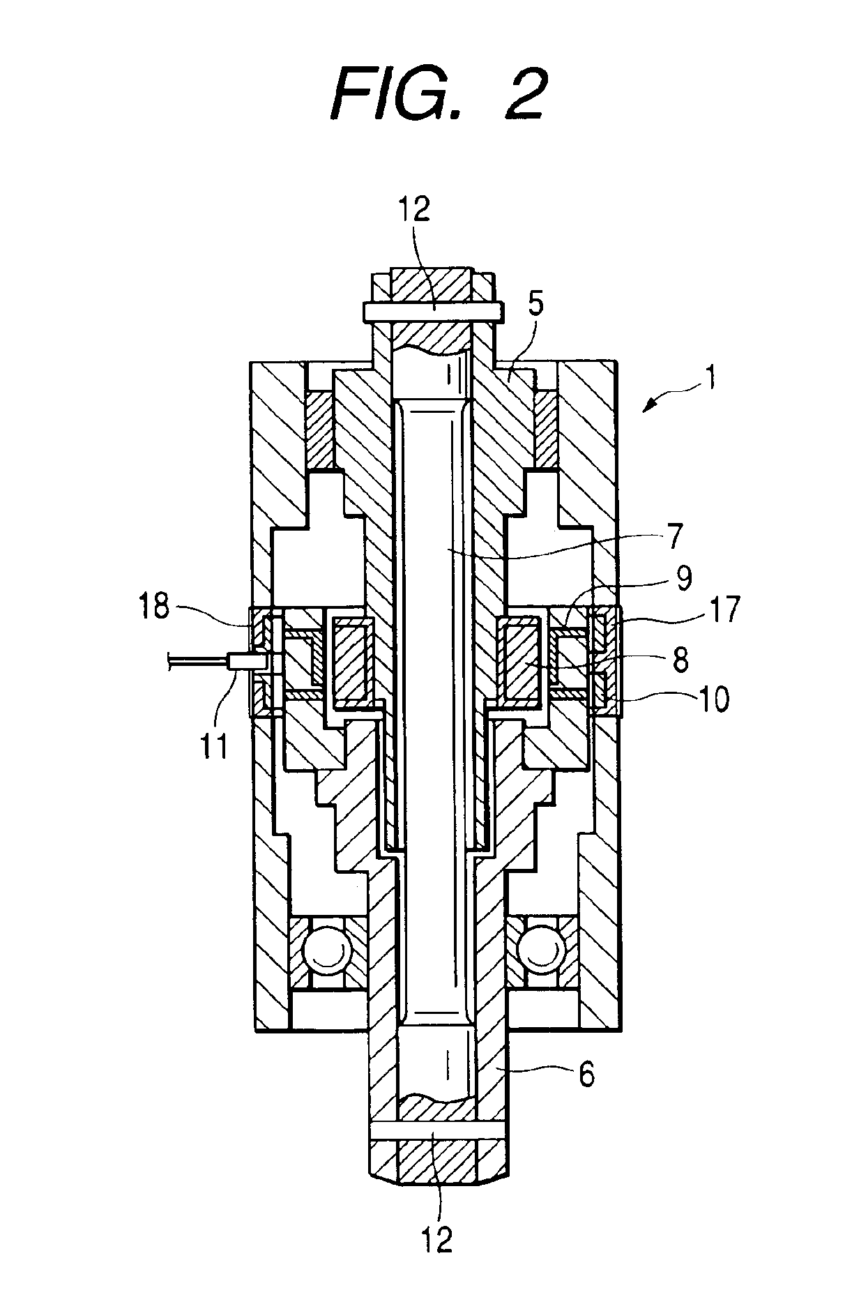
[0036]As shown in FIG. 2, the torsion bar 7 is an elastic rod member having one end connected to the input shaft ...

Example

Second Embodiment

[0052]FIG. 9 is a perspective view showing an assembly of one set of flux collecting rings 10 being integrated by resin molding and assembled with a magnetic shield 18 in accordance with another embodiment.

[0053]As shown in FIG. 10B, the magnetic shield 18 of this embodiment has side portions 18b at both ends in axial lateral direction so as to be configured as a whole into U shaped in cross section.

[0054]As shown in FIG. 9, the side portions 18b of magnetic shield 18 cover the side surfaces of the molding member 17. Thus, it becomes possible to greatly reduce the adverse influence given by the external magnetic field. The detection error of the magnetic sensor 11 can be further reduced.

Modified Embodiment

[0055]According to the first embodiment, the magnetic shield 18 is later fixed to the assembly of the set of flux collecting rings 10 after the resin molding operation is accomplished. It is however possible to integrate the set of flux collecting rings 10 and the ...


PUM


Abstract

A first shaft and a second shaft are connected coaxially. A torsion bar converts a torque applied between two shafts into a torsion displacement. A multipolar magnet is fixed to the first shaft. One set of magnetic yokes is fixed to the second shaft and disposed in a magnetic field generated by the multipolar magnet. One set of flux collecting rings is disposed along an outer surface of the set of magnetic yokes and opposed to each other via an air gap in an axial direction. A magnetic sensor is provided for detecting the density of magnetic flux generated in the air gap. An outer cylindrical surface of the set of flux collecting rings is surrounded by a magnetic shield.

Description

BACKGROUND OF THE INVENTION[0001]This invention relates to a torque sensor detecting a shaft torque applied to a rotary shaft as change of magnetic flux density (i.e., strength of magnetic field).[0002]As a conventional technique, Japanese Patent Application Laid-open No. 2003-149062 (FIG. 15) discloses a torque sensor.[0003]This torque sensor is, for example, used for a motor-driven power steering apparatus. As shown in FIG. 11, an input shaft 100 and an output shaft 110 are coaxially connected by a torsion bar 120. A multipolar magnet 130 is fixed to the input shaft 100. One set of magnetic yokes 140, fixed to the output shaft 110, is disposed in a magnetic field generated from the multipolar magnet 130. One set of flux collecting rings 150 collecting magnetic fluxes generated from the magnetic yokes 140. A magnetic sensor 160 detects the density of magnetic flux generated in an air gap between the opposed flux collecting rings 150.[0004]The above-described conventional torque sen...

Claims


Application Information

Patent Timeline
IPC IPC(8): G01L5/22G01L3/10
CPCG01L3/101G01L5/221G01L3/104
Inventor NAKANE, NAOKIFUKAYA, SHIGETOSHI
Owner DENSO CORP
Why Eureka
Try Eureka