Thermostatic mixing valve unit

a technology of thermostatic mixing and valve unit, which is applied in the direction of gaseous heating fuel, stoves or ranges, instruments, etc., can solve the problems of unregulated water temperature at the discharge outflow, potential scalding of a person using the emergency wash station, and malfunction of the tempered water mixing system

Active Publication Date: 2016-01-12
HAWS CORP
View PDF16 Cites 8 Cited by
  • Summary
  • Abstract
  • Description
  • Claims
  • Application Information

AI Technical Summary

Problems solved by technology

In the past, tempered water mixing systems have on occasion encountered malfunction in the operation of the thermostatic mixing valve.
As one example, the mixing valve can stick in a position providing unregulated water flow, wherein too much hot water can result in potential scalding of a person using the emergency wash station.
In another failure mode, either one of a pair of hot and cold water check valves can stick in a closed position thereby preventing flow of hot or cold water to the mixing valve and resultant unregulated water temperature at the discharge outflow.
In the event of a power failure, the back-up devices have generally failed to function, or otherwise have provided for only cold water flow.
In addition, during normal operation, the electrically operated components can cycle back-and-forth, so that a user is subjected to alternating brief flows of water that are either too hot or too cold.
Further, electrically powered back-up devices are unsuitable for many industrial applications wherein the emergency wash station must be located in close proximity to volatile materials.
However, this system as shown and described in U.S. Pat. No. 5,350,112 does not account for failure of the cold water inflow to the main mixing valve, as can occur upon sticking of a cold water check valve in a closed position.

Method used


Image

  • Thermostatic mixing valve unit
  • Thermostatic mixing valve unit
  • Thermostatic mixing valve unit

Examples


Embodiment Construction

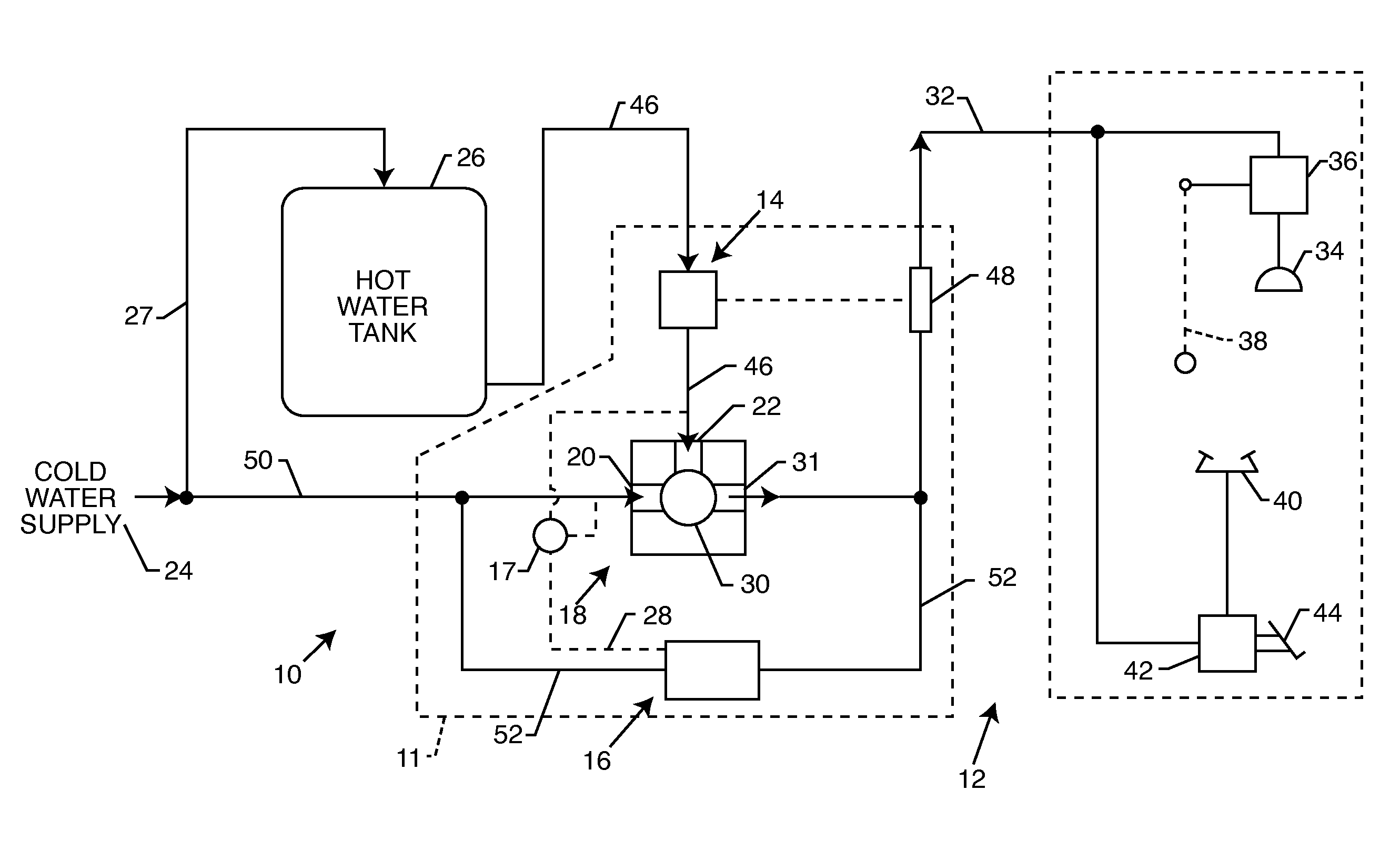
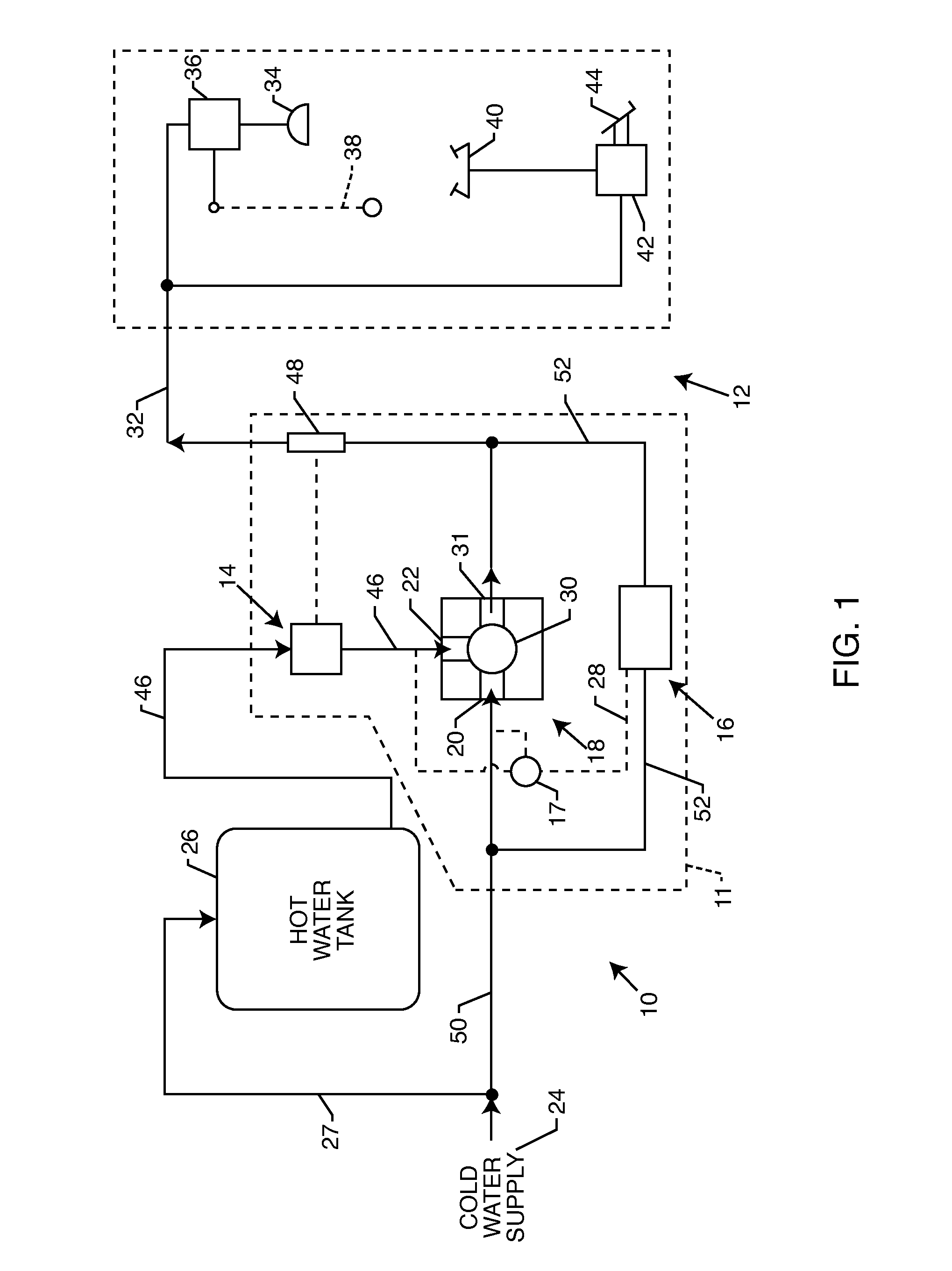
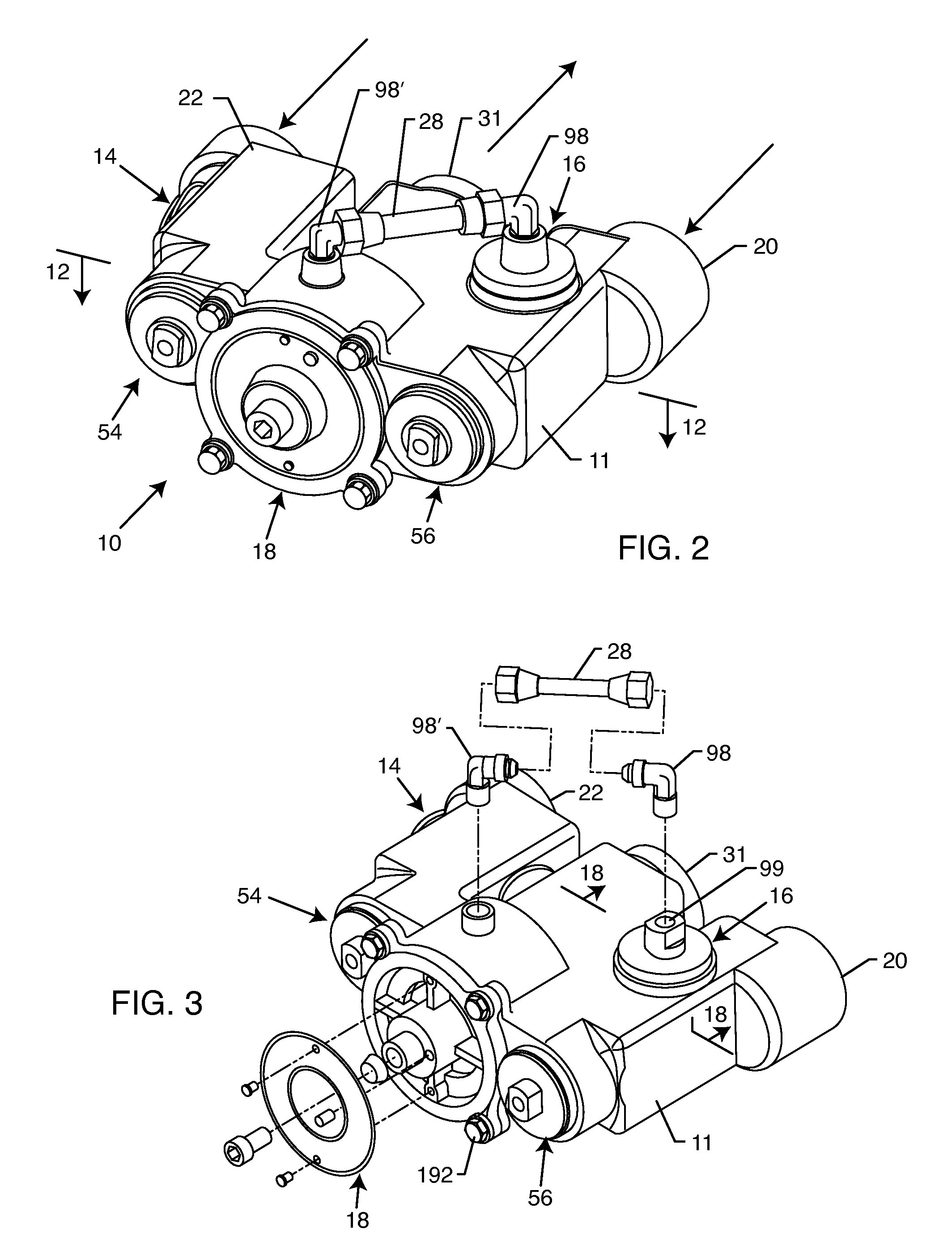
[0038]As shown in the exemplary drawings, an improved thermostatic mixing valve unit referred to generally in FIG. 1 by the reference numeral 10 is provided for use with an emergency wash station 12 such as the illustrative eyewash station and / or a drench-type shower station for flushing contaminants from a person's eyes, skin and clothing. The thermostatic mixing valve unit 10 comprises a substantially unitized or integrated housing 11 including a thermostatic mixing valve 18 having a cold water supply inlet 20, and a hot water supply inlet 22 for respectively receiving cold and hot water inflows. A thermostatic valve element (referred to schematically in FIG. 1 by the reference numeral 30) operates the mixing valve 18 to provide a tempered water outflow via an outflow port 31. A high temperature limit valve 14 includes a thermostatic element 48 mounted within the tempered water outflow for modulating or preventing hot water inflow to the mixing valve 18 in a manner to maintain a d...


PUM


Abstract

A thermostatic mixing valve unit in an emergency wash unit has an integrated housing with cold and hot water inlets each having an associated check valve, and a tempered water discharge having a thermostat for cold / hot water mixing to provide a predetermined tempered water discharge. A high temperature limit valve responds to the water discharge temperature to permit or prevent hot water inflow when the water discharge exceeds a preset temperature. A cold water bypass valve is coupled by a diverter valve to the lower of the cold and hot water supply pressures to maintain a substantial water discharge flow when the high temperature limit valve restricts hot water flow or when the hot water check valve is stuck closed, or upon failure of the cold water supply as by sticking of the cold water check valve in a closed position or by a clogged filter screen.

Description

BACKGROUND OF THE INVENTION[0001]This invention relates generally to improvements in thermostatic mixing valve units and systems of the type generally shown and described in U.S. Pat. No. 5,350,112, for use with an emergency wash station, such as an eyewash station and / or a shower station. More specifically, this invention relates to an improved thermostatic mixing valve unit of substantially unitary or integrated construction having an internal high temperature limit valve for restricting hot water inflow upon a tempered water discharge exceeding a predetermined temperature level, in combination with a diverter valve for operating a cold water bypass valve to provide a substantial water discharge flow upon hot water restriction and / or failure of various system components.[0002]Thermostatic mixing valves and related systems are generally known in the art for use in emergency wash stations such as eyewash and / or shower stations designed to provide a tempered water discharge outflow a...

Claims


Application Information

Patent Timeline
Patent Type & Authority Patents(United States)
IPC IPC(8): G05D23/13G05D23/12F24C3/12
CPCG05D23/1346
Inventor GONCZE, ZOLTAN
Owner HAWS CORP
Why Eureka
Try Eureka