Antenna assembly and method of making same

a technology of antenna and assembly method, applied in the direction of antenna connectors, coupling device connections, lamination, etc., can solve the problems of user forgetting to position a connector, requiring additional assembly complexity, and completely unprotected electronic components of the electronic device, so as to simplify the assembly and protect the electronic device.

Active Publication Date: 2016-01-12
HIRSCHMANN CAR COMMUNICATION
View PDF2 Cites 3 Cited by
  • Summary
  • Abstract
  • Description
  • Claims
  • Application Information

AI Technical Summary

Benefits of technology

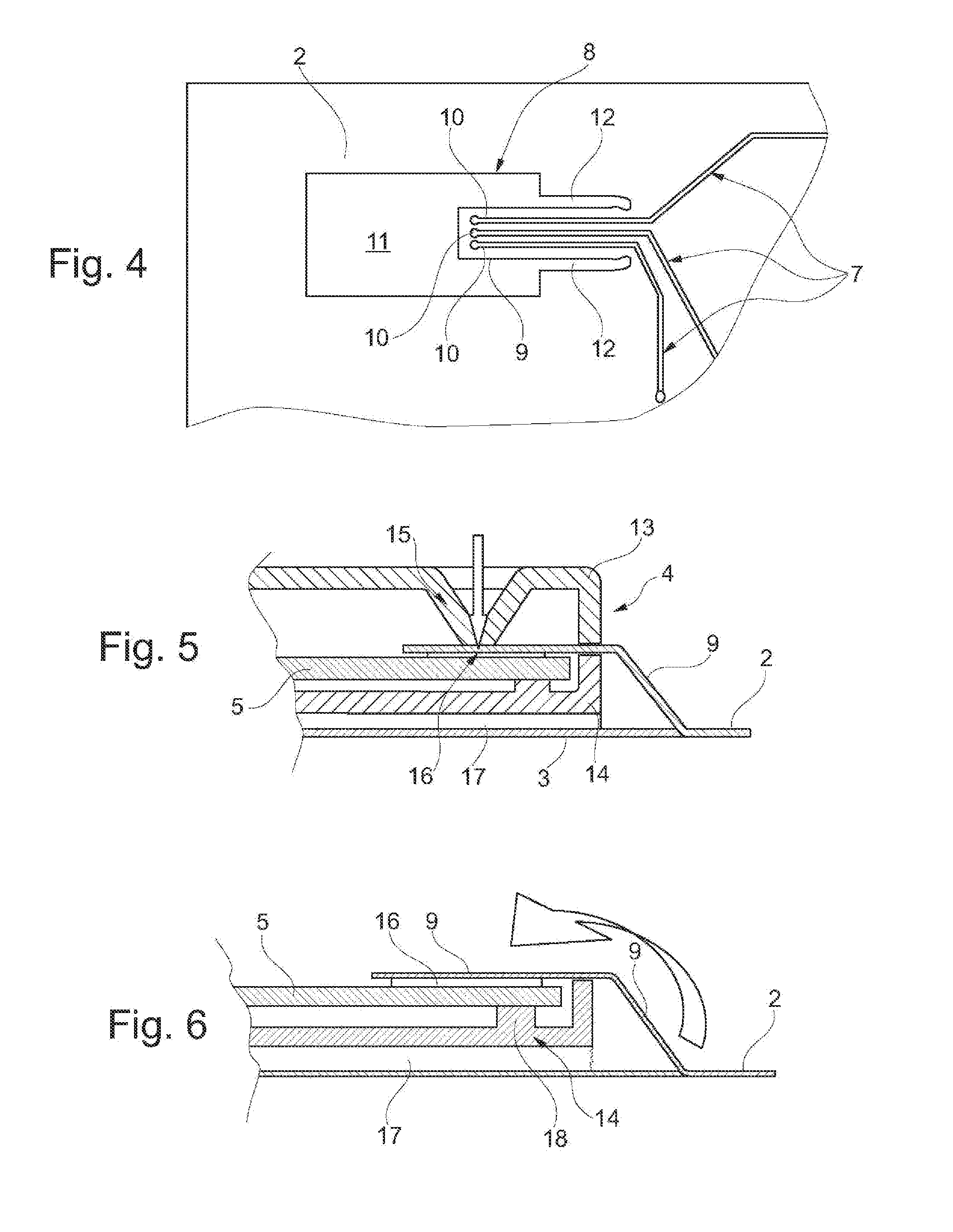
[0005]Regarding the antenna, the invention envisions mounting the electronic device (before assembly on the base film) inside a housing, the tab extending into the housing and the housing is provided on the base film in such a manner that it is fixed in place. On the one hand, the housing protects the electronic device against external influences. Moreover, this also translates into a simplification in terms of assembly, because the housing that contains the printed circuit board with the electronic components is mounted on the base film easily, quickly and without complication, for example by gluing. Connecting the ends of the antenna structures provided at the tab, can be achieved either prior to the assembly of the housing on the base film or thereafter. For example, the housing can include a slot into which the tab is inserted, and, following the completed insertion of the tab into the housing, connecting with the corresponding contact regions of the printed circuit board of the electronic device.
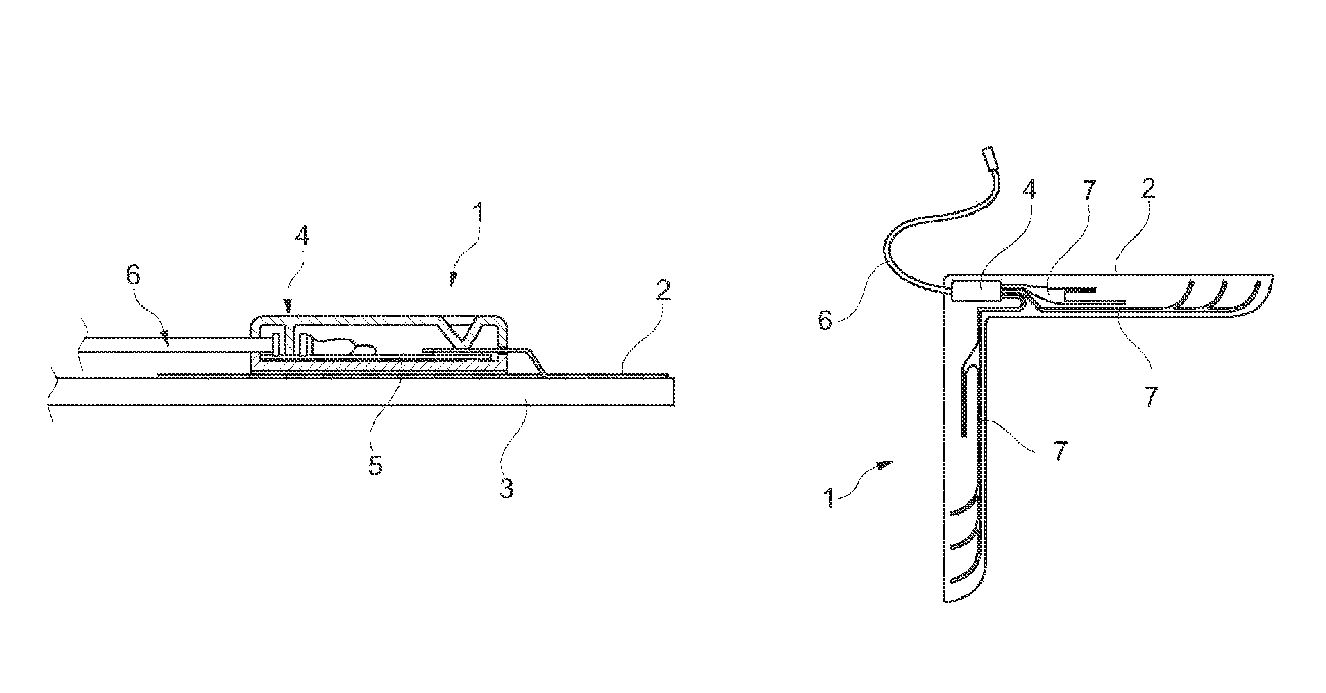
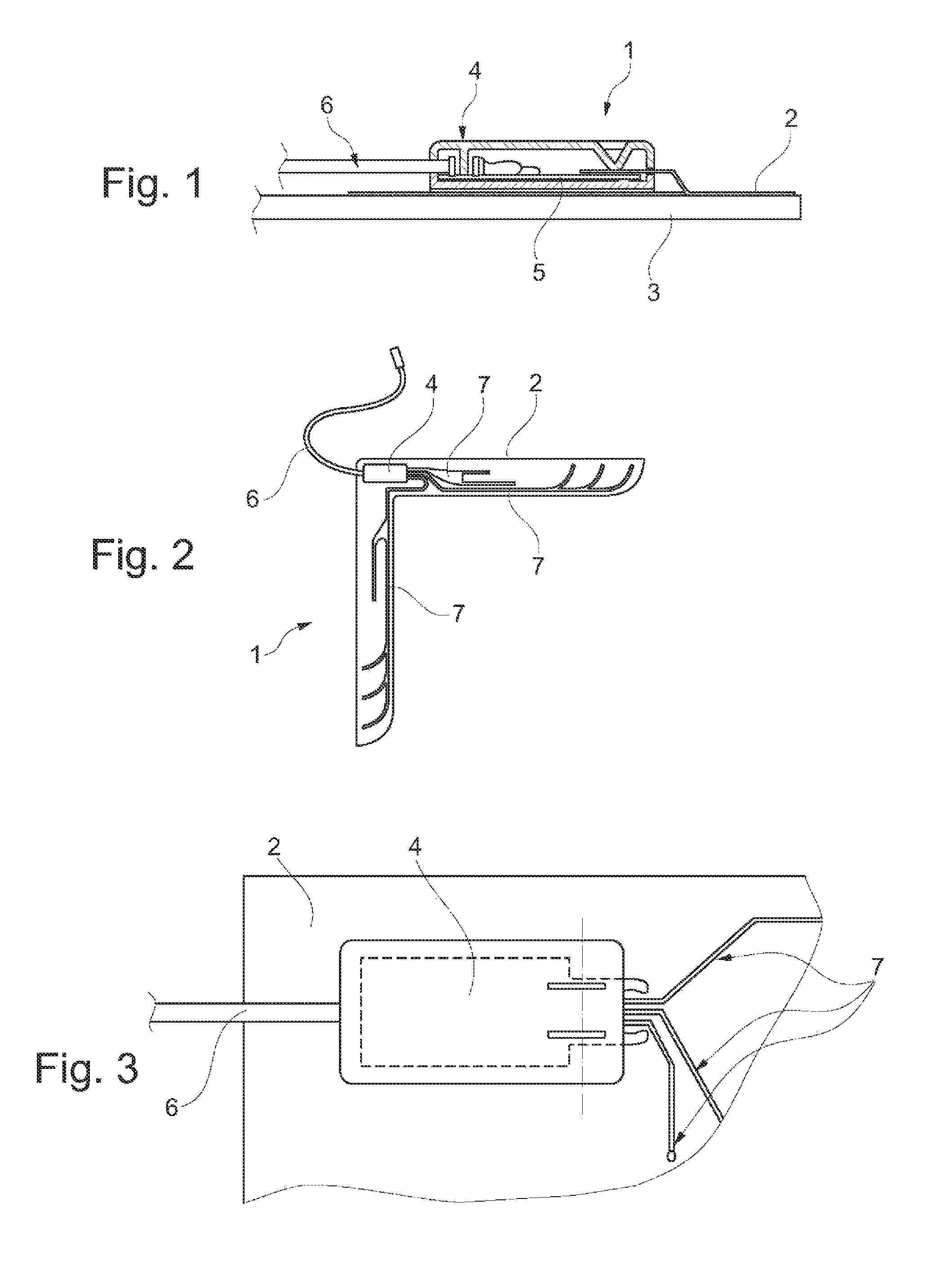
[0006]In an improvement of the invention, the tab forms a opening in the base film that is at least of equal size as it; and this opening is covered up by the housing of the electronic device. This means that the tab is provided within the base film (as opposed to on the edge thereof), for example by punching it out, and the contact regions of the antenna structures are located on the tab. It is then possible to flexibly insert the tab into the housing of the electronic device and establish contact with it therein. The tab simultaneously provides strain relief for the contact region, so it is impossible for temperature fluctuations, mechanical movements (in particular, vibrations) and the like to have a permanent negative effect on the contact region.
[0009]In an improvement of the invention, an adhesive layer is provided on a face of the housing that is directed toward the base surface, particularly of the bottom part. This adhesive layer has at least one first function. In fact, the adhesive layer serves for adhering the housing to the base film, particularly the bottom part. Before assembly of the housing, the adhesive layer is protected by a strip layer in such a manner that it is necessary to remove the strip layer before the housing can be glued onto the base film. This increases assembly speed, and current adhesive layers are suitable and constituted such that the housing is permanently and immovably provided on the base film. Moreover, the adhesive layer has still another function. Due to the fact that the adhesive layer extends over the opening created by formation of the tab, it is possible to fasten the entire antenna on a vehicle component using only this part of the adhesive layer. This is because the tab is inserted into the housing, such that this results, preferably, in the opening being located below part of the total region. Using this opening, it is possible to connect the adhesive layer that is located on the bottom face of the housing with the vehicle component. Correspondingly, a further configuration of the invention provides for the adhesive layer to be covered up at least by one strip layer, if only the housing must be provided on the base film (covering up the opening, or not). Furthermore, it is also advantageous to provide a second strip layer that is removed after the first strip layer has been removed prior to the second strip layer and that is used for adhering the housing in place on the base film. In this case, it is possible to remove the second strip layer at a later time; namely when the antenna is to be mounted on the vehicle.
[0010]Regarding the method of making an antenna of this kind, the invention provides that the electronic device is provided inside a housing, the tab is inserted into the housing, and the housing is adhered in place on the base film. This results in the same advantages as described above with regard to the structural configuration of an antenna.
[0011]Furthermore, the invention envisions that an adhesive layer provided on the bottom face of the housing is covered up by at least one strip layer, preferably two strip layers, prior to the housing being fixed in place on the base film; and the at least one strip layer is removed in order to then glue the housing into a fixed position on the base film. This makes it possible to mount the housing, particularly the bottom part thereof, quickly and easily in a desired position on the base film.

Problems solved by technology

However, this has the disadvantage that the electronic device with the delicate electronic components thereof is completely unprotected.
Moreover, in a variant as described in the prior art, it is disadvantageous that the ends of the antenna structures that are located at the tab, must be connected to connectors, and the connectors are then brought into contact with complementary connectors of the electronic housing.
This requires additional complexity in terms of assembly; and there exists the risk that, when mounting the apparatus of the electronic device on the base film, the user forgets to position a connector.
As a result, the electronic device cannot function properly.

Method used


Image

  • Antenna assembly and method of making same
  • Antenna assembly and method of making same
  • Antenna assembly and method of making same

Examples


Embodiment Construction

[0021]As shown in FIG. 1, an antenna 1 has a base film 2. Antenna structures are mounted for carrying-out receiving and / or transmitting functions on this base film 2. The antenna 1 is provided on a support 3, and a housing 4 with a printed circuit board 5 is permanently fixed on the base film 2. The electronic components are located as required on the printed circuit board 5 for carrying out the desired receiving and / or transmitting functions or signal-processing operations. On the output side, the printed circuit board 5 is connected to an antenna cable 6. This antenna cable 6 connects the electronic device (configured, for example, as an adjustment device, amplifier, signal processor or the like) to a further electronic device located downstream, not shown here.

[0022]FIG. 2 shows the antenna 1 with the base film 2, the housing 4 of the electronic device, as well as the antenna cable 6. One or more antenna structures 7 are provided as required on the base film 2. In this case, the ...


PUM

PropertyMeasurementUnit
shapeaaaaaaaaaa
sizeaaaaaaaaaa
temperatureaaaaaaaaaa

Abstract

An antenna having a base film carrying at least one antenna structure and one electronic device with a contact region of the at least one antenna structure being provided on a tab formed from the base film and contacted with a contact region of the electronic device is made by first providing the electronic device inside a housing. Then the tab is inserted into the housing. Finally the housing is adhesively adhered in place on the base.

Description

CROSS REFERENCE TO RELATED APPLICATIONS[0001]This application claims the priority of German patent application 10 2012 002 182.8 filed 7 Feb. 2012.FIELD OF THE INVENTION[0002]The invention relates to an antenna as well as a method of making such an antenna according comprising a base film carrying at least one antenna structure and an electronic device, a contact region of the at least one antenna structure being constituted as a tab formed from the base film and contacted with a contact region of the electronic device.BACKGROUND OF THE INVENTION[0003]DE 10 2005 009 443 discloses an antenna formed as a film antenna for a vehicle. This antenna has a base film having at least one antenna structure, and an electronic device, a contact region of the at least one antenna structure being mounted on a tab formed by the base film, and contacted with a contact region of the electronic housing. The electronic device has a printed circuit board carrying electronic components in order to perfor...

Claims


Application Information

Patent Timeline
Patent Type & Authority Patents(United States)
IPC IPC(8): H01Q1/50H01Q1/22H01Q1/12H01P11/00H01R12/79H01Q23/00H01Q1/32H01Q1/20
CPCH01Q1/50H01Q1/1271H01Q1/20H01Q1/22H01Q1/325H01Q23/00H01R12/79H01R2201/02Y10T156/1052
Inventor SILVA, DAVID
Owner HIRSCHMANN CAR COMMUNICATION
Why Eureka
Try Eureka