
Methods for joint optimization of link equalization

a technology of equalization and optimization methods, applied in the field of transmission of data across communication links, can solve the problems of becoming increasingly difficult to achieve the goal of achieving the desired bit error rate (ber) target, and achieve the effect of equalization sufficient to achieve the targ

Active Publication Date: 2016-01-12
ALTERA CORP
View PDF40 Cites 6 Cited by
  • Summary
  • Abstract
  • Description
  • Claims
  • Application Information

AI Technical Summary

Benefits of technology

The patent text describes a method for selecting equalization settings for a transmitter and a receiver in a computer-implemented system. The method uses different processes depending on the signal-to-noise ratio and the capability of the transmitter and receiver. The method selects a set of candidate settings for transmitter equalization or a single setting through auto adaptation. The method also optimizes the receiver continuous-time linear equalization based on the channel model, tap selection, and a figure of merit. The method can account for various factors such as phase-locked loops, driver and receiver circuitry, equalization schemes, and channel conditions. The patent text also provides an article of manufacture that implements the method. The technical effects of the patent text include improved signal quality, reduced noise, and improved system performance.

Problems solved by technology

As the operating speed of the high-speed serial links increases to rates which are tens of gigabits per second (Gbps) or more, it has become increasingly challenging to perform equalization sufficient to achieve desired bit error rate (BER) targets.

Method used


Image

  • Methods for joint optimization of link equalization
  • Methods for joint optimization of link equalization
  • Methods for joint optimization of link equalization

Examples


Embodiment Construction

[0017]Finding optimal transmitter and receiver equalization settings in a joint manner is highly challenging due to complex channel characteristics and a very large search space for the transmitter and receiver equalization settings. For example, a transmitter may have tens of thousands of equalization settings, and a receiver may have tens of millions of equalization settings. Hence, in this example, the combined search space may have several hundreds of billions of possible equalization settings.

[0018]Searching such a large parameter space is prohibitive in terms of computational time and resources. As such, conventional approaches typically optimize the transmitter and receiver equalization settings separately without taking into account each other, rather than interactively and jointly. This often results in sub-optimal settings.

[0019]The present disclosure provides three optimization processes that cover a wide variety of applicable link and device configurations. In addition, ...


PUM


Abstract

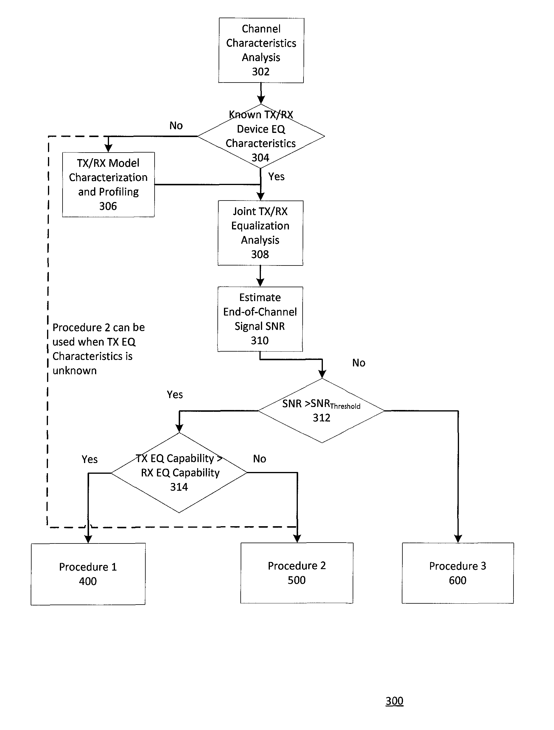
One embodiment relates to a computer-implemented method that selects one of at least three procedures to determine equalization settings jointly for a transmitter and a receiver. A first process may be used if the end-of-channel signal-to-noise ratio (SNR) is greater than an SNR threshold and the equalization capability of the transmitter is greater than the equalization capability of the receiver. A second process may be used if the end-of-channel SNR is greater than the SNR threshold and the equalization capability of the transmitter is less than the equalization capability of the receiver. A third process may be used if the end-of-channel SNR is less than the SNR threshold. Other embodiments and features are also disclosed.

Description

TECHNICAL FIELD[0001]The present invention relates generally to the transfer of data across communication links.DESCRIPTION OF THE BACKGROUND ART[0002]High-speed serial links are used to communicate data between devices in a system. Serial interface protocols have been developed at increasingly fast data rates for such high-speed links. Examples of industry-standard protocols for serial interfaces include PCI Express® (Peripheral Component Interconnect Express), XAUI (X Attachment Unit Interface), sRIO (serial Rapid IO), and others.[0003]As the operating speed of the high-speed serial links increases to rates which are tens of gigabits per second (Gbps) or more, it has become increasingly challenging to perform equalization sufficient to achieve desired bit error rate (BER) targets. In order to achieve the desired BER targets, both transmitter equalization and receiver equalization may be used.SUMMARY[0004]One embodiment relates to a computer-implemented method that selects one of m...

Claims


Application Information

Patent Timeline
IPC IPC(8): H03H7/30H03K5/159H04L25/03
CPCH04L25/03885H04L25/03019H04L25/03343H04L2025/03471H04L2025/03802H04L2025/03636
Inventor WU, HSINHOSHIMANOUCHI, MASASHILI, PENG
Owner ALTERA CORP
Learn More