Fuel flowmeter having an improved regulator device

a technology of flowmeter and regulator device, which is applied in the direction of valve operating means/releasing devices, functional valve types, machines/engines, etc., can solve the problems of creating head loss between the second chamber and the third chamber, and achieve the effect of reducing the pressure difference between the outlet and the inlet of the metering valv

Active Publication Date: 2016-01-19
SAFRAN HELICOPTER ENGINES
View PDF18 Cites 3 Cited by
  • Summary
  • Abstract
  • Description
  • Claims
  • Application Information

AI Technical Summary

Benefits of technology

[0020]As a result, the return circuit is opened and the pressure difference between the outlet and the inlet of the metering valve is decreased. It can thus be understood that the regulator device of the flowmeter of the invention keeps this pressure difference constant in spite of the diaphragm being damaged. Under such circumstances, it is thus the piston, the two springs, the channel, and the valve member that act advantageously as an emergency regulator device.
[0021]During normal operation of the diaphragm, the piston does not move and the channel makes it possible to ensure that the pressure in the second spring corresponds to the pressure of fuel at the outlet from the metering valve. The valve member is then free to move relative to the piston, on the same principle as in the prior art flowmeter.
[0023]This adjustment rod enables the preload on the spring to be adjusted and thus enables the predetermined value for the pressure difference that it is desired to maintain across the metering valve to be adjusted.
[0026]One advantage is to avoid supplying an undesirable additional flow rate to the engine by providing the fuel with a path in parallel with the metering valve 114.
[0028]By way of example, an advantage may be to increase the flow rate so that the system controlling the metering valve can detect malfunction of the diaphragm. Suitable choices for the dimensions of the piston, for the stiffness, and for the prestress of the second spring 164 then enable the pressure difference across the metering valve to be adjusted to the same value, regardless of the state of the diaphragm. The flowmeter then delivers the same flow rate regardless of the state of the diaphragm. Nevertheless, in the event of the diaphragm being damaged, the designer may seek to increase the flow rate in controlled manner so that an effect is produced on the device consuming the metered fluid, but without that effect being dangerous for that device. Thus, the pilot may advantageously be informed that the pressure difference is now being regulated by the cage, the valve member, the first spring, and the second spring.

Problems solved by technology

The fuel then flows through the channel, which then acts as a nozzle, thereby creating head loss between the second chamber and the third chamber.

Method used


Image

  • Fuel flowmeter having an improved regulator device
  • Fuel flowmeter having an improved regulator device
  • Fuel flowmeter having an improved regulator device

Examples


Embodiment Construction

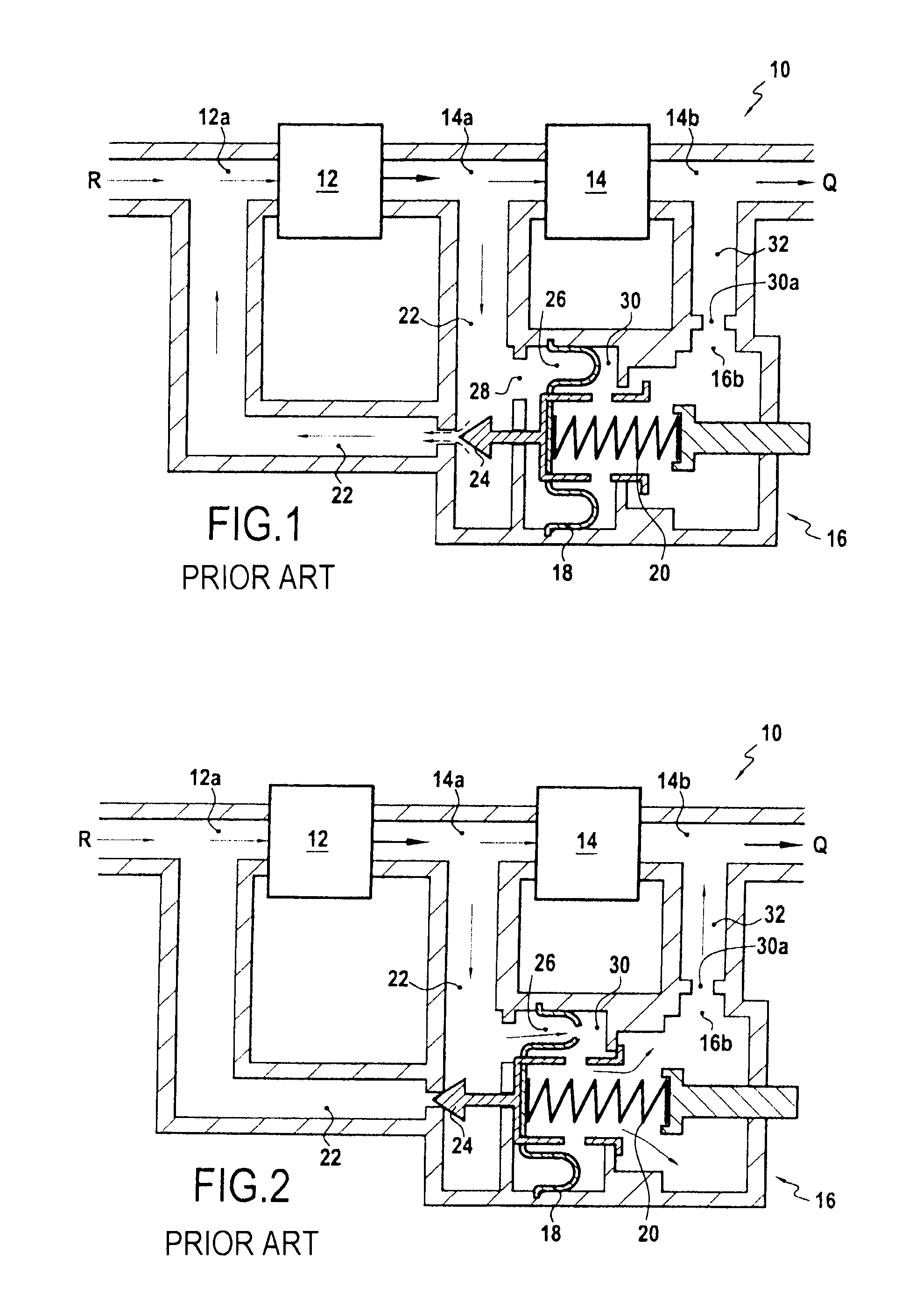
[0045]FIG. 1, which shows the prior art fuel flowmeter, is described in part above in the introduction to the description. It is specified that the pump is connected to a fuel tank R and that the regulator device 16 has a first chamber 26 in communication with the return circuit 22. This communication preferably takes place via an opening 28 formed upstream from the valve member 24.

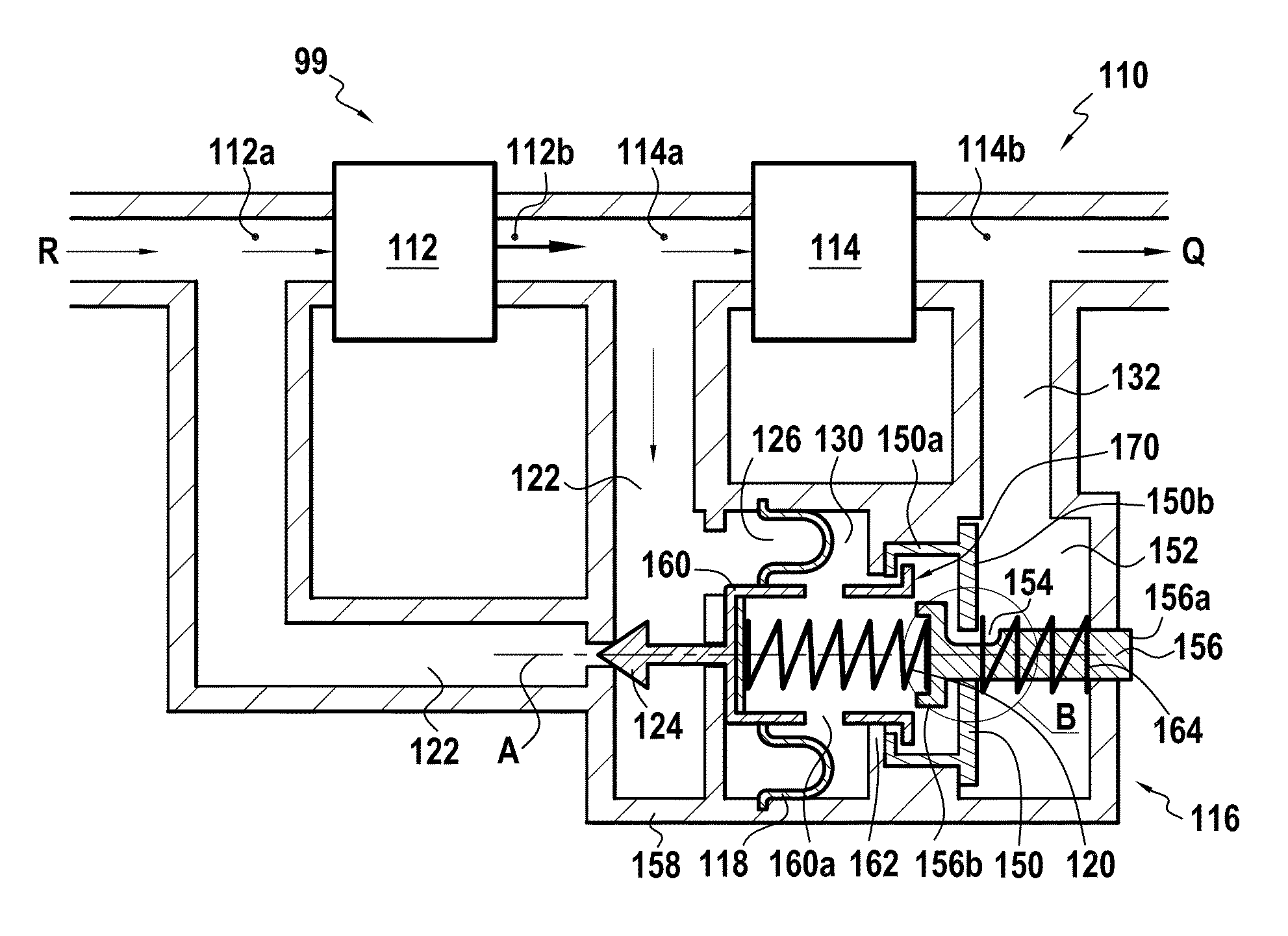
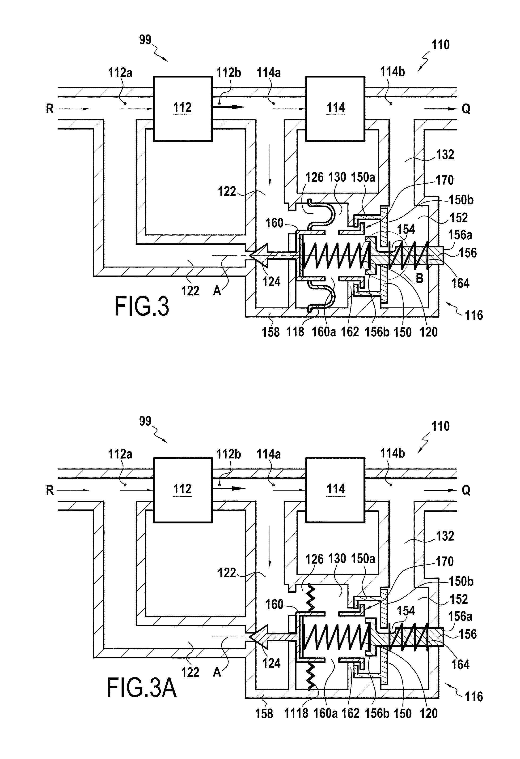
[0046]In normal operation, this first chamber is defined in particular by the detection surface 18, specifically a flexible diaphragm, such that the pressure in the first chamber is equal to the pressure at the inlet 14a to the metering valve 14.

[0047]The prior art regulator device also includes a second chamber that is defined by the diaphragm 18 and that communicates with an outlet circuit 32 connecting the outlet 16b of the regulator device to the outlet 14b of the metering valve 14. It can thus be understood that the pressure of fuel in the second chamber is equal to the pressure at the outlet 14b of ...


PUM


Abstract

A fuel flowmeter for being fed by a pump including an inlet and an outlet, including: a metering valve including an inlet and an outlet, and arranged downstream from the outlet of the pump; a return circuit connecting the inlet of the metering valve to the inlet of the pump; and a pressure regulator device including: a movable valve member to close and open the return circuit, a pressure difference detection surface fastened to the valve member and axially separating a first chamber in communication with the inlet of the metering valve from a second chamber in communication with the outlet from the metering valve, a piston axially separating the second chamber from a third chamber connected to the outlet of the metering valve, and a channel putting the second chamber in communication with the third chamber.

Description

FIELD OF THE INVENTION[0001]The present invention relates to the field of regulating the feed of fuel through an engine such as a turbine engine of an aircraft.BACKGROUND OF THE INVENTION[0002]More particularly, the present invention relates to a fuel flowmeter for being fed by a pump having an inlet and an outlet, said flowmeter comprising:[0003]a metering valve having an inlet and an outlet, said valve being arranged downstream from the outlet of the pump;[0004]a return circuit connecting the inlet of the metering valve to the inlet of the pump; and[0005]a pressure regulator device comprising a movable valve member suitable for closing and opening the return circuit, a pressure difference detection surface fastened to the valve member and axially separating a first chamber in communication with the inlet of the metering valve from a second chamber in communication with the outlet from the metering valve, a first spring arranged in the second chamber while being fastened to the det...

Claims


Application Information

Patent Timeline
Patent Type & Authority Patents(United States)
IPC IPC(8): F16K31/12F02C7/232F02C9/26
CPCF02C7/232F02C9/263F05D2270/3015Y10T137/7773
Inventor BENEZECH, PHILIPPE JEAN RENE MARIEFACCA, BRUNOLEGLISE, LUDOVIC ALEXANDREZORDAN, CEDRIC ROGER
Owner SAFRAN HELICOPTER ENGINES
Why Eureka
Try Eureka