
Load and consumer

a load and consumer technology, applied in the field of load and a system, can solve the problems of complicated and expensive, difficult installation of t-pieces, and inability to meet the needs of customers, and achieve the effect of simple and cost-effective wiring

Active Publication Date: 2016-01-19
SEW-EURODRIVE GMBH & CO KG
View PDF22 Cites 0 Cited by
  • Summary
  • Abstract
  • Description
  • Claims
  • Application Information

AI Technical Summary

Benefits of technology

[0004]Example embodiments of the present invention to provide simpler and more cost-effective wiring in electrical loads and systems.
[0006]This allows for a quick connection to and disconnection from the power supplying system. It is not necessary to use exposed electrical contacts. In addition, the insertion part made of plastic is inexpensive to manufacture.
[0007]In this context, it may be provided that the load may be manufactured in a cost-effective manner to be impervious and to provide a high degree of protection, for the contactless powering of the load allows the housing to be manufactured simply and easily, in particular without uneven areas or plug-and-socket connectors, and therefore allows water to drain off and the settling of solids to be prevented. Therefore, it is particularly suitable in wet areas and aseptic areas. Example embodiments of the present invention may allow the time necessary for wiring to be reduced. In addition, leakage currents that occur in conventional plug-and-socket wiring are prevented, which means that improved electromagnetic compatibility is produced.
[0008]The power supply to the loads may be voltageless, and the carrying-over of voltage otherwise present in systems, as well as spark-suppression devices in disconnecting switches, may be eliminated. In addition, reactive-power compensation is made possible, in particular in the load, and therefore the alternating current has smaller values, which is why smaller wire diameters may be provided in the case of primary conductors and lower wiring costs are therefore attainable. Disconnecting switches may be eliminated, since interruption may be replaced by extraction of the primary conductor.
[0013]A primary conductor may be provided on the load such that an inductive coupling to a secondary winding contained by the load is providable. In this context, it may be provided that a plug-and-socket connector is not necessary, and the wiring may therefore be carried out in a simple and rapid manner. In addition, it is possible to reduce costs. Since it is not necessary to precut the cable and fit it with connectors, the installation may also be carried out by employees not trained in electrical technology.
[0018]It may be provided that the load does not include a plug-and-socket connector or other electrical connection terminals on its exterior. In this context, the load may be easily manufactured to be impervious and to provide a high degree of protection.LIST OF REFERENCE CHARACTERS

Problems solved by technology

These T-pieces are difficult to install and expensive, in particular when they must be usable and provide a high degree of protection in wet areas or even aseptic areas.
Therefore, they are complicated and expensive, especially with regard to installation as well.

Method used


Image

  • Load and consumer
  • Load and consumer
  • Load and consumer

Examples


Embodiment Construction

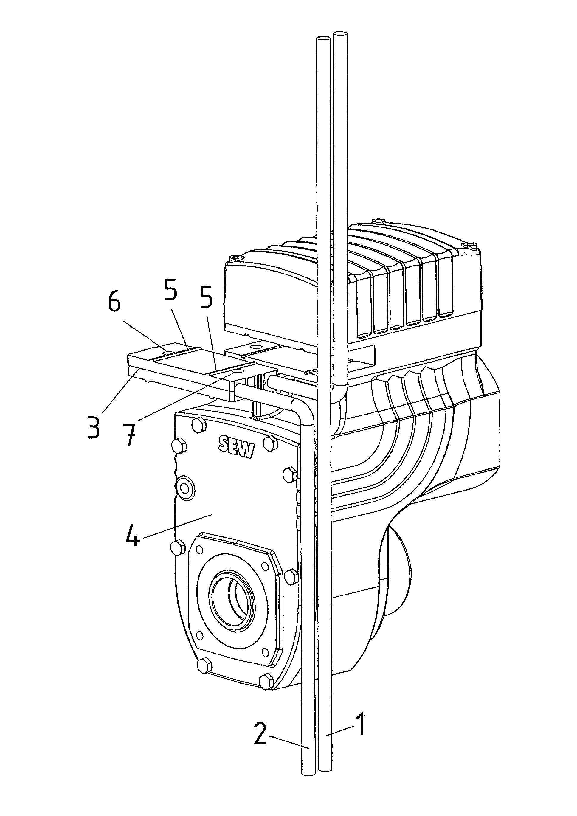
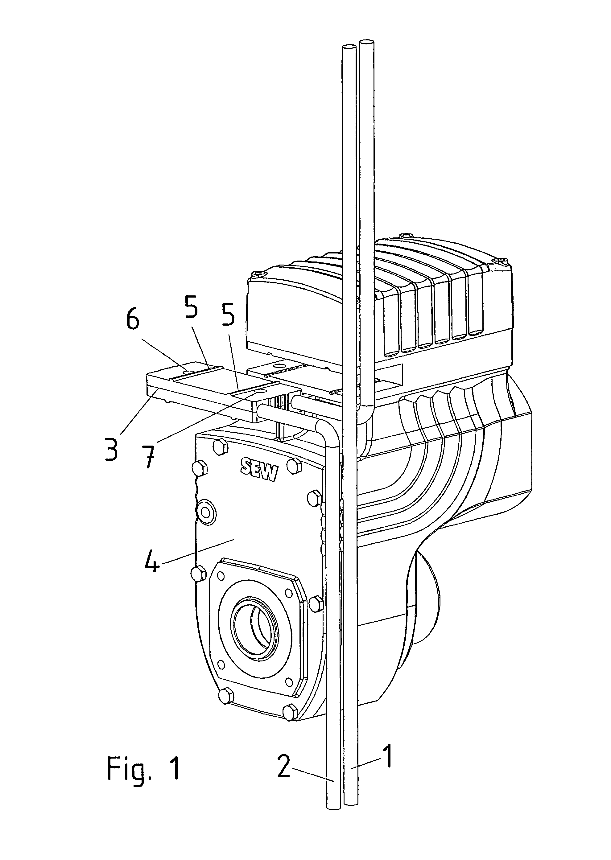
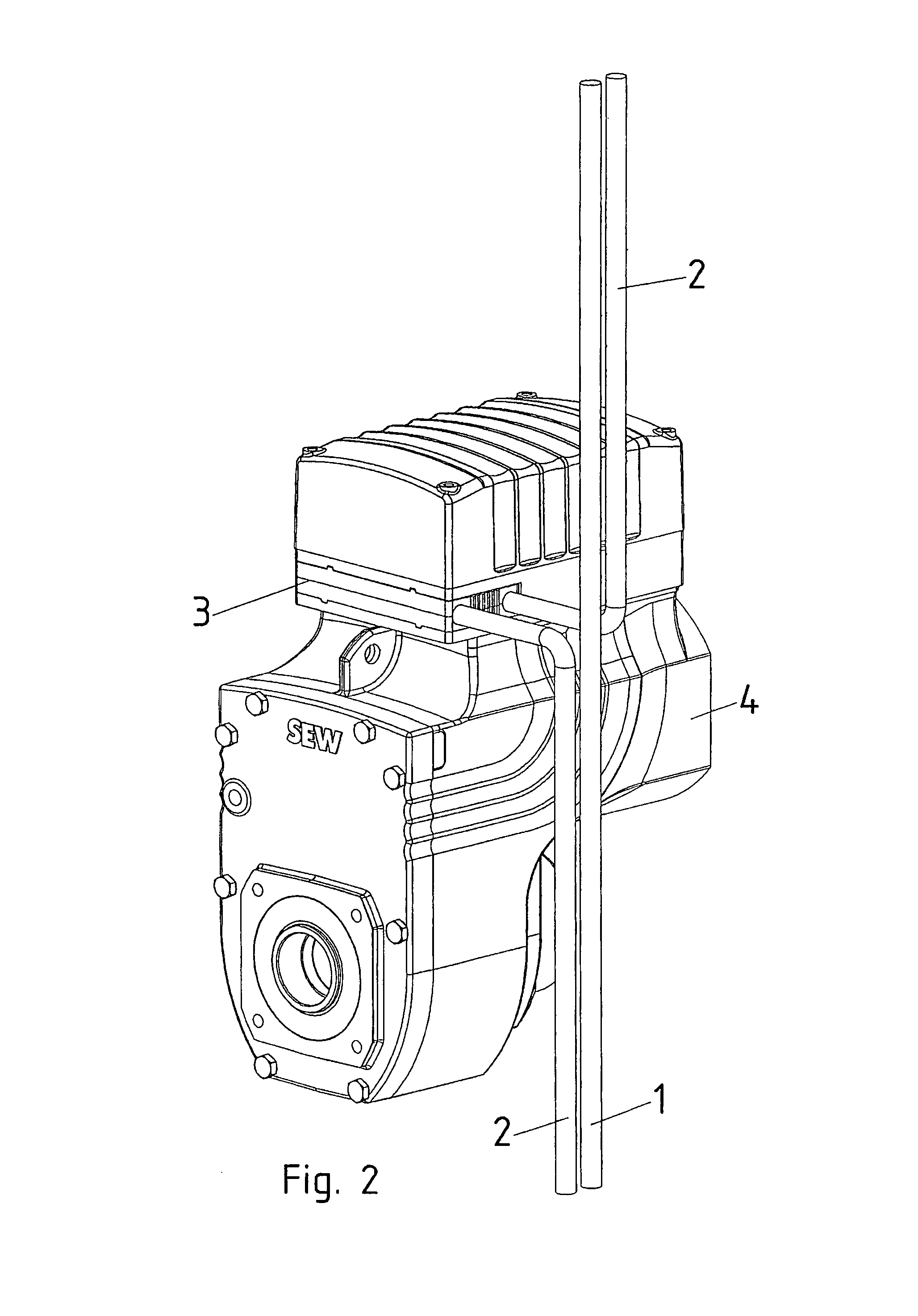
[0029]The primary conductor system includes a supply conductor 1 and a return conductor 2, in which a medium-frequency alternating current is applied.

[0030]Load 4, taking the form of a converter gear motor, includes a secondary winding, which, following the insertion of insertion part 3, is inductively coupled to the primary conductor system.

[0031]Insertion part 3 has elevations 5 for a form-locking connection to load 4 or at least as a guide when inserting insertion part 3. Bore holes 6, 7 are additionally provided.

[0032]Using a bolt, which can be inserted through bore hole 6 and also inserted into a bore hole of the load, it is possible to couple insertion part 3 to load 4 in a form-locking manner. For this purpose, a tool is required, and only operators using the tool are able to release the connection.

[0033]When insertion part 3 has been taken out of the load, a padlock may be inserted by its shackle into bore hole 7. In this manner, it is possible to block the reinsertion of th...


PUM


Abstract

A load includes a device for inductively powering it, the device including an insertion part, following the insertion of which into the load the powering of the latter is provided.

Description

FIELD OF THE INVENTION[0001]The present invention relates to a load and a system.BACKGROUND INFORMATION[0002]In industrial plants, it is conventional that electrical loads, such as electronic devices, lighting devices, drives, machines, etc., can be powered galvanically from a network, in particular using alternating current at 50 or 60 Hz. To this end, the loads are mostly mechanically attached and electrically connected by expensive plug-and-socket connectors. In addition, most of such systems or machines have a T-piece for each drive unit as an energy branch. These T-pieces are difficult to install and expensive, in particular when they must be usable and provide a high degree of protection in wet areas or even aseptic areas. These T-pieces are also referred to as distribution boxes and often include additional device parts as well, such as emergency-off switches. Therefore, they are complicated and expensive, especially with regard to installation as well.[0003]German Published ...

Claims


Application Information

Patent Timeline
Patent Type & Authority Patents(United States)
IPC IPC(8): H02J3/00H02J5/00H02K5/22H02K11/00
CPCH02J5/005H02K5/225H02K11/0094H02K11/33H02K11/0073Y10T307/297H02J50/10H01F27/2823
Inventor SCHMIDT, JOSEF
Owner SEW-EURODRIVE GMBH & CO KG
Learn More