
Air-cooled hard hat

a technology of hard hats and cooling devices, which is applied in the direction of helmets, helmet covers, headwear, etc., can solve the problem that construction projects often involve work

Active Publication Date: 2016-01-26
INNOVATIVE DESIGN CONCEPTS
View PDF26 Cites 17 Cited by
  • Summary
  • Abstract
  • Description
  • Claims
  • Application Information

AI Technical Summary

Benefits of technology

The invention provides a hard hat with an air circulation feature that allows air to flow into the hat through an opening in the shell and out through a fan arrangement. The fan arrangement can be controlled by the user to direct air towards the interior of the hat or the user's face. This feature improves comfort and helps to keep the hat cool in hot conditions.

Problems solved by technology

It is well known that construction projects often involve work during hot conditions.
While providing increased air movement and comfort to the user, mans' of these options are heavy or bulky headgear which may be distracting or uncomfortable for a user accustomed to a standard hard hat.

Method used


Image

  • Air-cooled hard hat
  • Air-cooled hard hat
  • Air-cooled hard hat

Examples


first embodiment

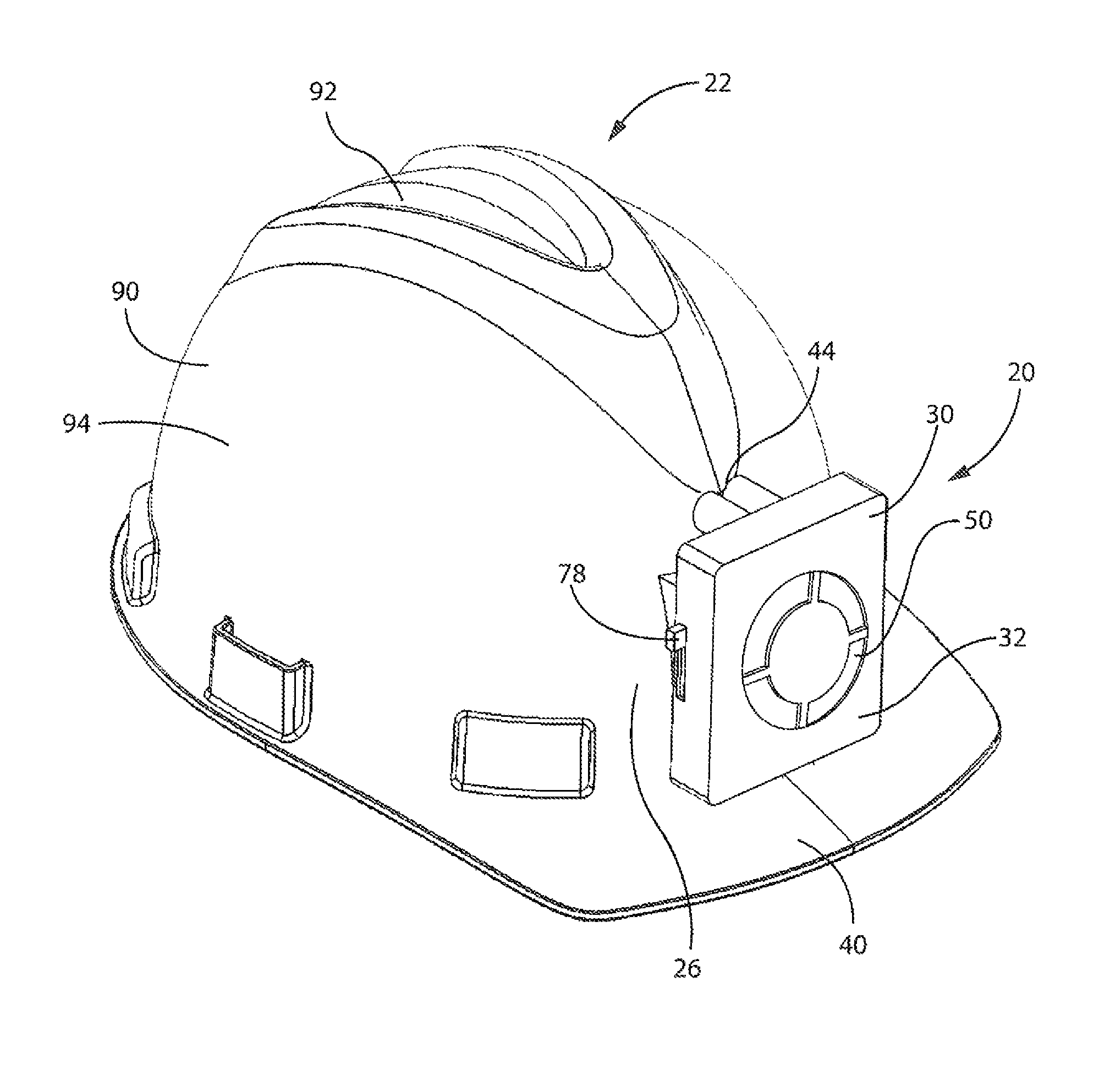
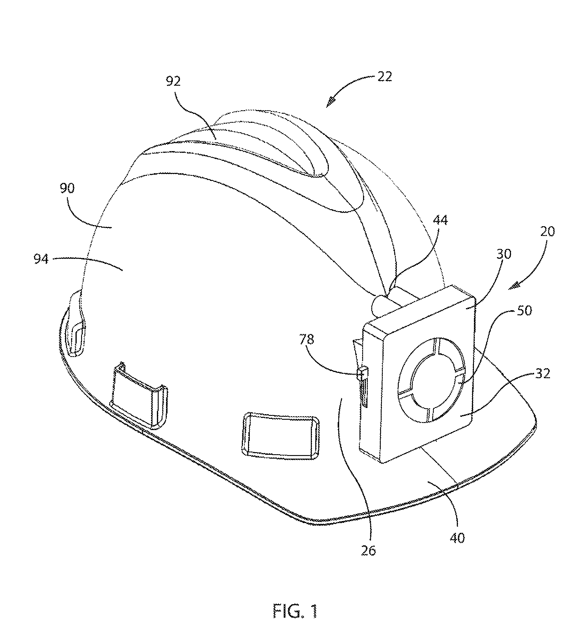
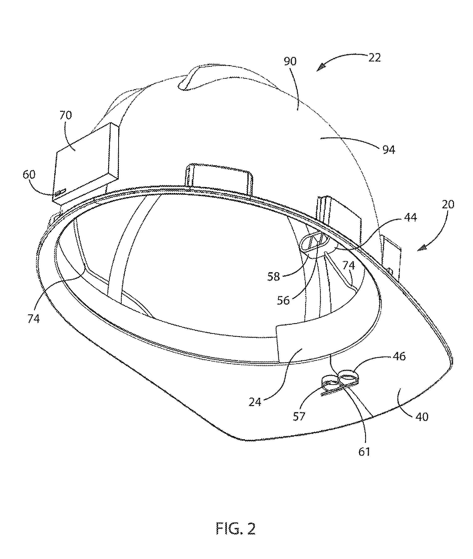
[0037]Referring now to FIGS. 1-9, a fan arrangement 20 consists of a housing 30 that may be made of durable, but lightweight material. For instance, in one embodiment, the housing 30 may be made of a hard plastic. In the illustrated embodiment, the housing 30 is of a generally rectangular shape, and has a front side 32, a back side 34, and a bottom side 36. The front side. 32 has an air intake section 50 that allows air to be drawn into the housing 30 by a fan 52. The fan 52 is located within the housing 30, and is operated by a small motor 54. On the back side 34 of the housing 30 is an outlet 56 through which the air is pushed out of the housing through the exit 53 of the fan 52. In the illustrated embodiment, the outlet 56 has a diffuser 58 which has several grooves that function to distribute the air in a variety of directions. The grooves 59 of the diffuser 58 help to ensure that air is distributed laterally along the interior of the hard hat 22. Other configurations of diffuse...

second embodiment

[0042]Referring now to FIGS. 10-18, the present invention features a fan assembly 20a with only one outlet 56a. In this embodiment, the fan arrangement 20a consists of a housing 30a that may be made of durable, but lightweight material. For instance, the housing 30a may be made of a hard plastic. In the illustrated embodiment, the housing 30a is of a generally rectangular shape, and has a front side 32a, a back side 34a, and a bottom side 36a. The front side 32a has an air intake section 50a that allows air to be drawn into the housing 30a by a fan 52a. The lint 52a is located within the housing 30a, and is operated by a small motor 54a. On the back side 34a of the housing 30a is an outlet 56a through which the air is pushed out of the housing through the exit 53a of the fan 52a. In the illustrated embodiment, the outlet 56a has a diffuser 58a which has several grooves that function to distribute the air in a variety of directions. The grooves 59a of the diffuser 58a help to ensure ...


PUM


Abstract

An air-cooled hard hat includes a hard hat and a fan arrangement. The fan arrangement has a fan, an input, and at least one outlet for distribution of air. An opening is made on the hard hat, which the at least one outlet feeds through. The opening may be located on the front face of a laterally facing wall of the hard hat. When the fan arrangement is attached to the hard hat, the outlet provides air to the interior of the hard hat through the hole. Additionally, another opening may be located along a front brim of the hard hat. A second outlet that feeds through the opening in the brim provides air down onto the face of the user.

Description

BACKGROUND OF THE INVENTION[0001]1. Field of the Invention[0002]The present invention relates in general to the field of hard hats. More particularly, the present invention relates to a fan arrangement cooling device that can be installed on a standard, traditional hard hat with little modification of the hard hat.[0003]2. Discussion of the Related Art[0004]It is well known that construction projects often involve work during hot conditions. Nevertheless, workers are normally required to wear appropriate safety gear including hard hats at all times when on a job site. As a result, a variety of different products have been introduced to help ensure an increased level of comfort in warm temperatures.[0005]For instance, there are a number of specially made hard hats that include various cooling devices and fans within these configurations. One such configuration features a specially designed hard hat having a removable temperature panel that slides out such that a cooling pack or heati...

Claims


Application Information

Patent Timeline
Patent Type & Authority Patents(United States)
IPC IPC(8): A42B3/28
CPCA42B3/286
Inventor DANELSKI, DARIN, L.
Owner INNOVATIVE DESIGN CONCEPTS
Learn More