Driving circuit and illumination device having light-emitting elements

Inactive Publication Date: 2015-04-23
WISDOM TECH HLDG
View PDF6 Cites 6 Cited by
  • Summary
  • Abstract
  • Description
  • Claims
  • Application Information

AI Technical Summary

Benefits of technology

[0006]In summary, the driving circuit and the illumination device for the light-emitting elements of the present invention, increase the plurality of the switches and the switch-controlling circuit. Each of the switches is connected to two terminals of one light-emitting element or some light-emitting elements connected in series. The switch-controlling circuit controls the switches in the on state or in the off state according to the instantaneous value of the DC voltage outputted from the rectifying circuit, for controlling the amount of the light-emitting

Problems solved by technology

Therefore, the supernumerary part of the DC voltage of the driving circuit at any one time after rectifying are pointlessly consumed by the first current-cont

Method used


Image

  • Driving circuit and illumination device having light-emitting elements
  • Driving circuit and illumination device having light-emitting elements
  • Driving circuit and illumination device having light-emitting elements

Examples


Example

First Exemplary Embodiment

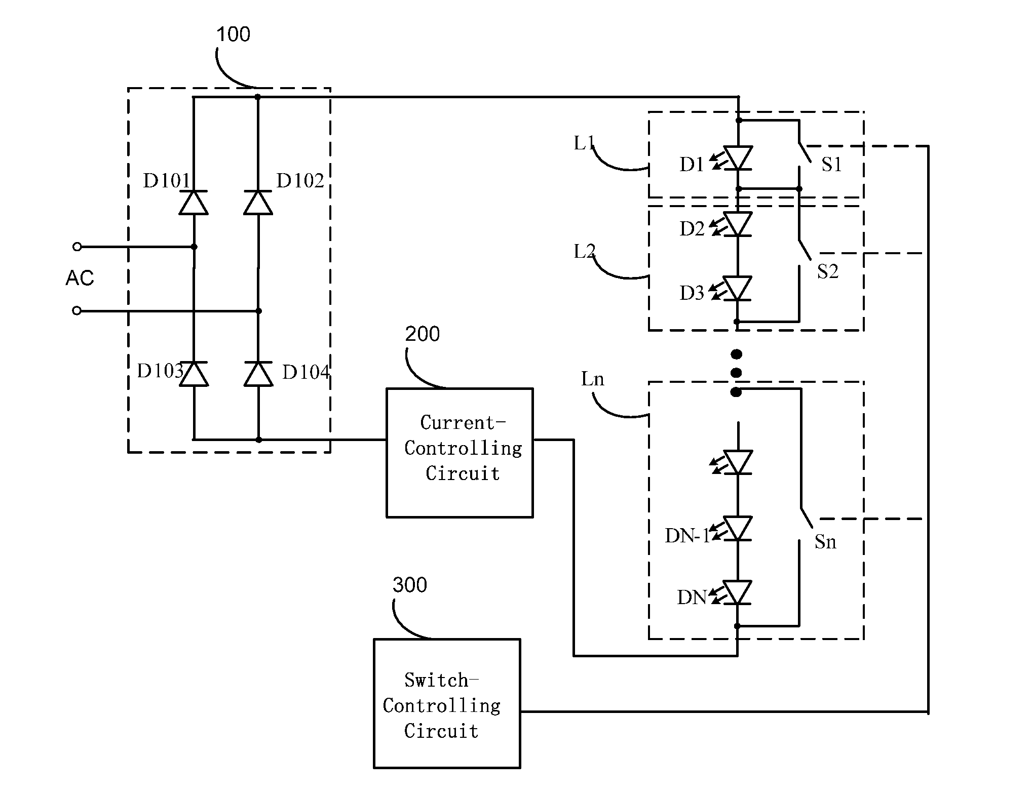
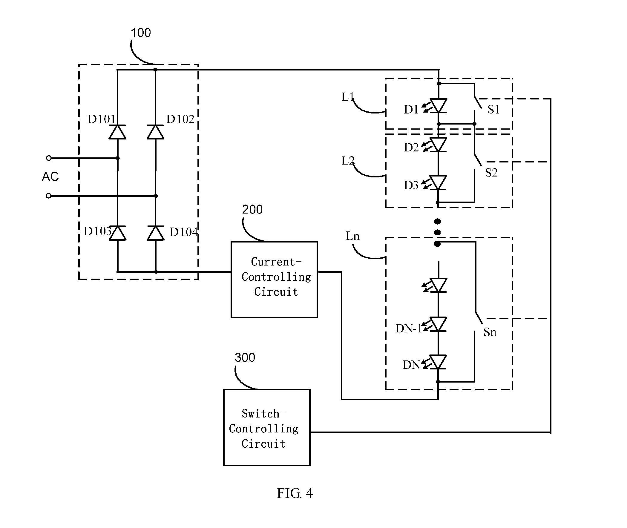
[0020]FIG. 4 is a circuit diagram of a driving circuit of a light-emitting element in accordance with a first exemplary embodiment of the present invention. The driving circuit of the light-emitting element comprises a rectifying circuit 100, a first current-controlling circuit 200, a plurality of switches (S1, S2, . . . , Sn), and a switch-controlling circuit 300.

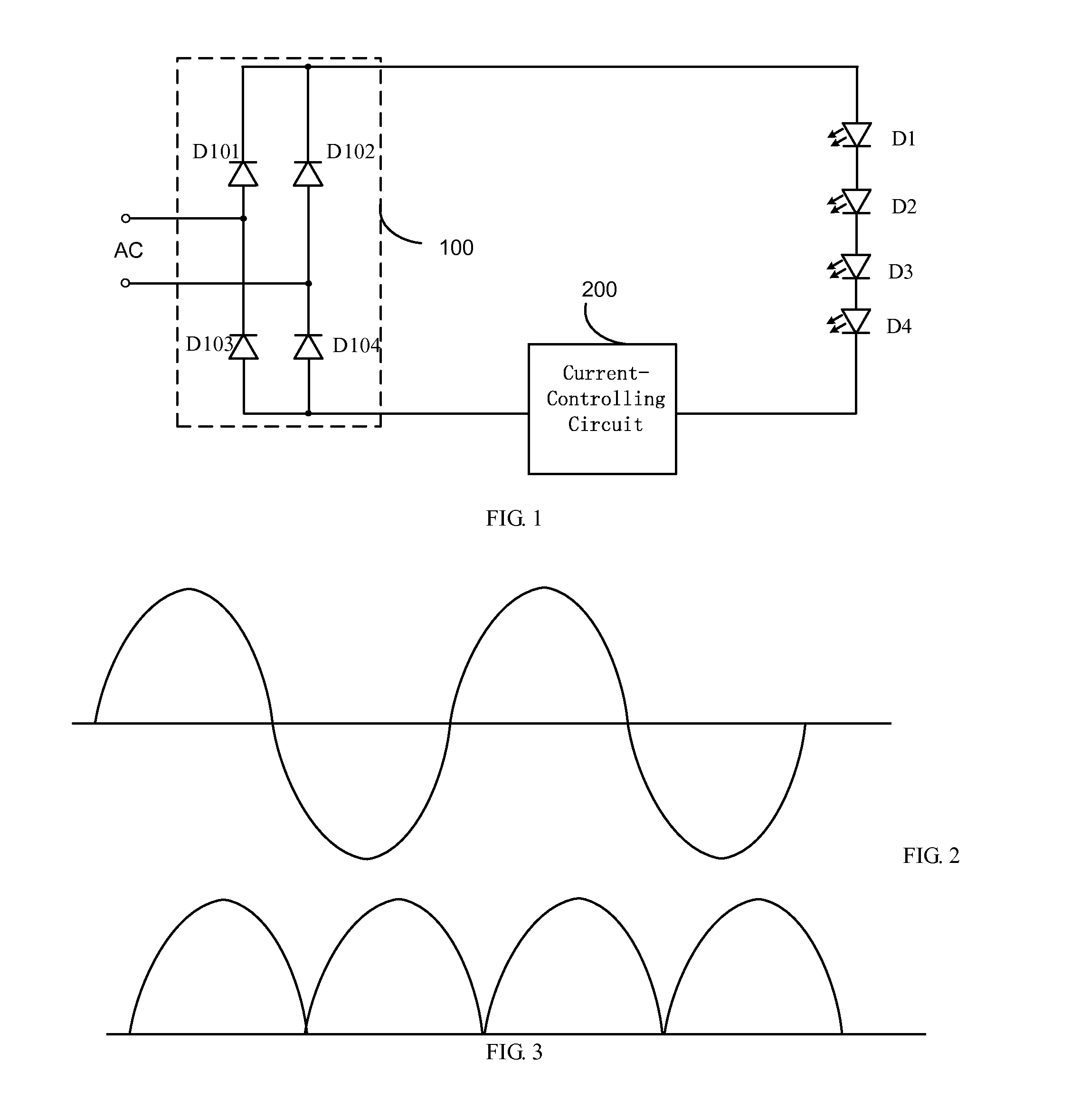
[0021]Wherein, the rectifying circuit 100 is a full-wave rectifying circuit consisted of four diodes D101, D102, D103, D104. Input terminals of the rectifying circuit 100 are connected to output terminals of an alternating-current input power source AC, and configured for rectifying the alternating-current input power source AC (waves as shown in FIG. 2) into a direct-current voltage (waveform as shown in FIG. 3). It should be noted that, the rectifying circuit 100 also can be a half-wave rectifying circuit consisted of one or two diodes, instead of the full-wave rectifying circuit consisted of fo...

Example

Second Exemplary Embodiment

[0030]Differences between this exemplary embodiment and the first exemplary embodiment are that, in this exemplary embodiment there are n light-emitting element subunits connected in serial, and amounts of light-emitting elements connected in parallel with switches of each of the n light-emitting element subunits are configured as a sequence consisted of the powers of 2. However, in the first exemplary embodiment, amounts of light-emitting elements connected in parallel in each of the light-emitting elements subunits are random, thus some numbers (such as 1, or 14) cannot be performed by the combinations, and it cannot completely provide the control of lightening one to the number of the whole light-emitting elements in series. In this exemplary embodiment, the amounts of the light-emitting elements connected in parallel with each switches are set to be the powers of 2, thus it can satisfy any one number from 1 to N1, and the sum of the amounts of the ligh...

Example

Third Exemplary Embodiment

[0037]Differences between this exemplary embodiment and the second exemplary embodiment are that, in this exemplary embodiment, the amounts of light-emitting elements connected in parallel with each of the switches are set to be the power of 2, but the sum N1 of the light-emitting elements of each of the light-emitting element subunits is larger than 2n-1−1 but less than 2n−1, that is, the it does not distribute the light-emitting elements of the powers of 2 to the switches respectively. In the second exemplary embodiment, N1 is equal to 2n−1, thus it can distribute the light-emitting elements of the powers of 2 to the switches respectively. This exemplary embodiment cannot distribute the light-emitting elements of the power of 2, but the combinations still can select any number from 1 to N1.

[0038]In the driving circuit, the amount of the switches is n, and an m-th switch is connected in parallel with two terminals of Am light-emitting elements connected in...


PUM


Abstract

The present invention discloses a driving circuit including a rectifying circuit and a first current-controlling circuit. Input terminals of the rectifying circuit are connected to output terminals of an AC power source. The first current-controlling circuit and a plurality of light-emitting elements be driven are connected in series, and then are connected between two output terminals of the rectifying circuit. The driving circuit further includes a plurality of switches and a switch-controlling circuit; the switches are connected in parallel with two terminals of one or some light-emitting elements connected in series to form many light-emitting element subunits. Control-signal output terminals of the switch-controlling circuit are connected to control terminals of the switches respectively, to control the switches in an ON-OFF state according to an instantaneous value of a DC voltage outputted from the rectifying circuit, for controlling an amount of light-emitting elements which should be lighten.

Description

TECHNICAL FIELD[0001]The present invention relates to a driving circuit and an illumination device, and more particularly to a driving circuit and an illumination device having light-emitting elements.DESCRIPTION OF THE RELATED ART[0002]Light-emitting element may convert electric energy into light energy, and is a common device for illuminating or displaying. The conventional light-emitting element comprises light-emitting diode (LED), organic light-emitting diode (OLED), polymer light-emitting diode (PLED), and laser diode (LD), etc. Take the LED as an example, FIG. 1 is a circuit diagram of a conventional driving circuit of LEDs, which comprises a rectifying circuit 100 and a first current-controlling circuit 200. The driving circuit drives a number of light-emitting elements connected in series. Input terminals of the rectifying circuit 100 are connected to output terminals of an alternating-current (AC) power source. The first current-controlling circuit 200 is connected to four...

Claims


Application Information

Patent Timeline
IPC IPC(8): H05B33/08H01S5/06H05B44/00
CPCH05B33/0827H05B33/0896H01S5/06H05B45/48H05B45/44H05B47/10H05B45/46H05B45/60
Inventor MO, CHAT HOI
Owner WISDOM TECH HLDG
Why Eureka
Try Eureka