Controlled shared load casing jack system

a shared load and jack system technology, applied in the direction of drilling casings, drilling pipes, borehole/well accessories, etc., can solve the problems of limited heavy load situations, difficult removal of tubulars from wellbores, and difficulty in using elevators to pull tubulars from wellbores,

Inactive Publication Date: 2007-11-15
WEATHERFORD TECH HLDG LLC
View PDF19 Cites 6 Cited by
  • Summary
  • Abstract
  • Description
  • Claims
  • Application Information

AI Technical Summary

Benefits of technology

[0011] Embodiments relate to a wellbore tubular removal system having a gripping member for gripping a tubular in a wellbore, and a lifting member engagable with the gripping member for lifting the tubular, a force transfer assembly to transfer a lifting force from the lifting member to a first surface, a force distribution assembly to divide a lifting force between the surface, and a second surface. The lifting member is a jack, which in one embodiment includes one or more fluid operated pistons. The jack has a monitoring device for monitoring the lifting force in the lifting member. The monitoring device restricts the lifting force to the maximum force the first surface and the second may carry. The force distribution assembly is a second jack. The first surface may be a structure of the wellbore. For example, the first surface may be a blowout preventor, casing stub, or a well head of the wellbore. The second surface may be a portion of a rig floor or a rotary table. The force transfer assembly comprises a spacer spool, which rests on top of the first surface. The top of the spacer spool is engagable to the second jack. The second jack has a monitoring device for monitoring the lifting force in the second jack.
[0012] Embodiments described herein relate to a wellbore tubular removal apparatus having a tubular gripping member engaged to a first jack, a second jack configured to rest between a top of a structure and the first jack, and a force transferring assembly. The force transferring assembly engagable to the second jack and a surface of the wellbore, wherein a lifting force created by the first jack is transferred through the force transferring member to the surface. In one embodiment, the first jack comprises one or more fluid operated cylinders. The tubular removal apparatus includes a plate having an aperture through which the tubular may pass. The second jack includes an aperture which may have a semicircular configuration and one or more jacks. The second jack further includes an aperture through which the tubular may pass. The lifting force is distributed, shared and controlled between the structure and the surface upon actuation of the second jack.
[0013] Embodiment described herein relate to a method for removing a tubular in a wellbore by gripping the tubular, lifting the tubular with a lifting member, transferring a lifting force from the lifting member to a first surface via a force transferring member, and using a force transferring assembly to distribute, control and share the lifting force from the lifting member between a second surface and the first surface. The invention monitors the lifting force in the lifting member and the force transfer assembly and controls the amount of lifting force applied to the first surface and the second surface. The first surface and the second surface may be in separate horizontal planes and the tubular may be uncut coiled tubing.
[0014] Further, embodiments described herein relate to an apparatus for removing a tubular from a wellbore having a gripping member for gripping a tubular in the wellbore and a lifting member engagable with the gripping member for lifting the tubular. The lifting member comprises a jack. The jack having one or more fluid operated cylinders attachable to a plate, which may be a semicircular plate, at the top of the fluid operated cylinders. The jack having a second plate, which may be a semicircular plate, attachable to the bottom of the fluid operated cylinders. The lifting member is designed to straddle a tubular.

Problems solved by technology

Often such tubulars are stuck in the wellbore and therefore removal from the wellbore is difficult.
The use of an elevator to pull wellbore tubulars may be dangerous and limited under heavy load situations.
The movement of the gripping apparatus or cables after failure creates a great risk to workers and equipment on the drilling rig.
However, when lifting tubulars from the wellbore either on the rig floor or wellbore surface alone are often insufficient for supporting the load required to break the tubular out of the ground.
These approach is costly and time consuming.

Method used


Image

  • Controlled shared load casing jack system
  • Controlled shared load casing jack system
  • Controlled shared load casing jack system

Examples


Embodiment Construction

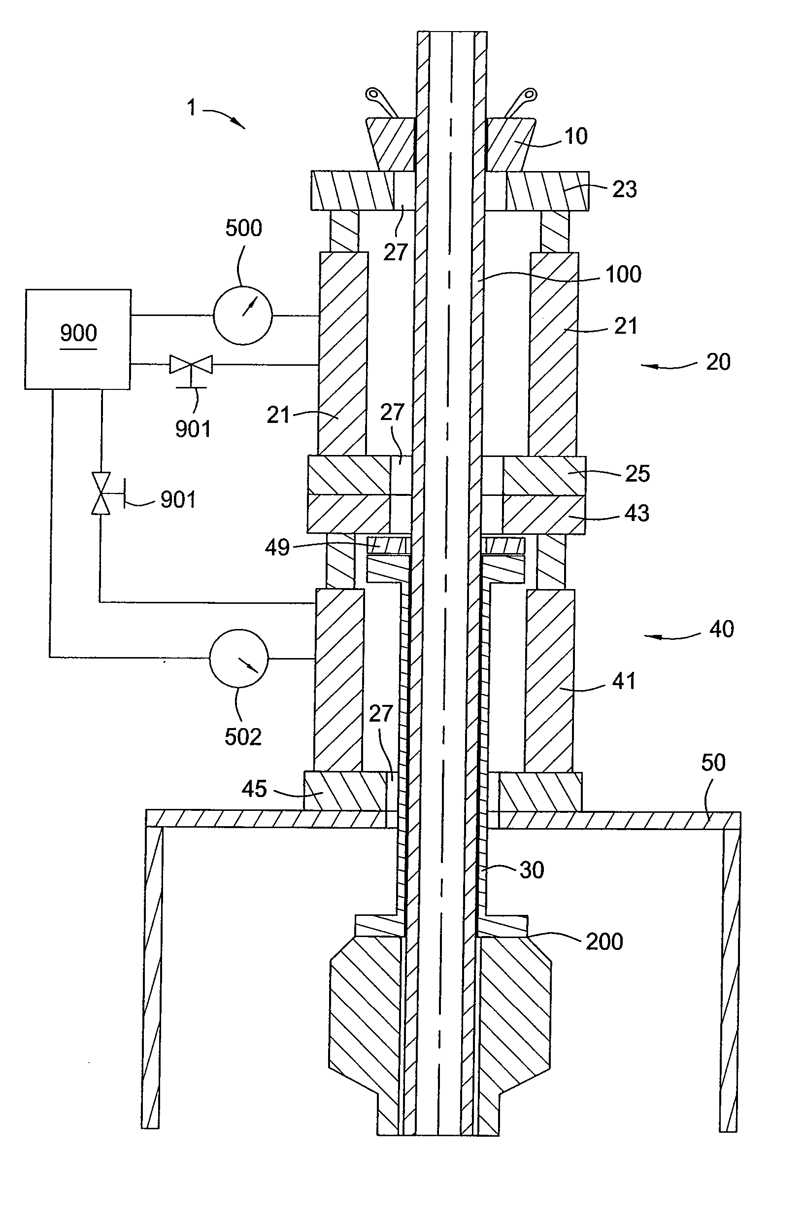
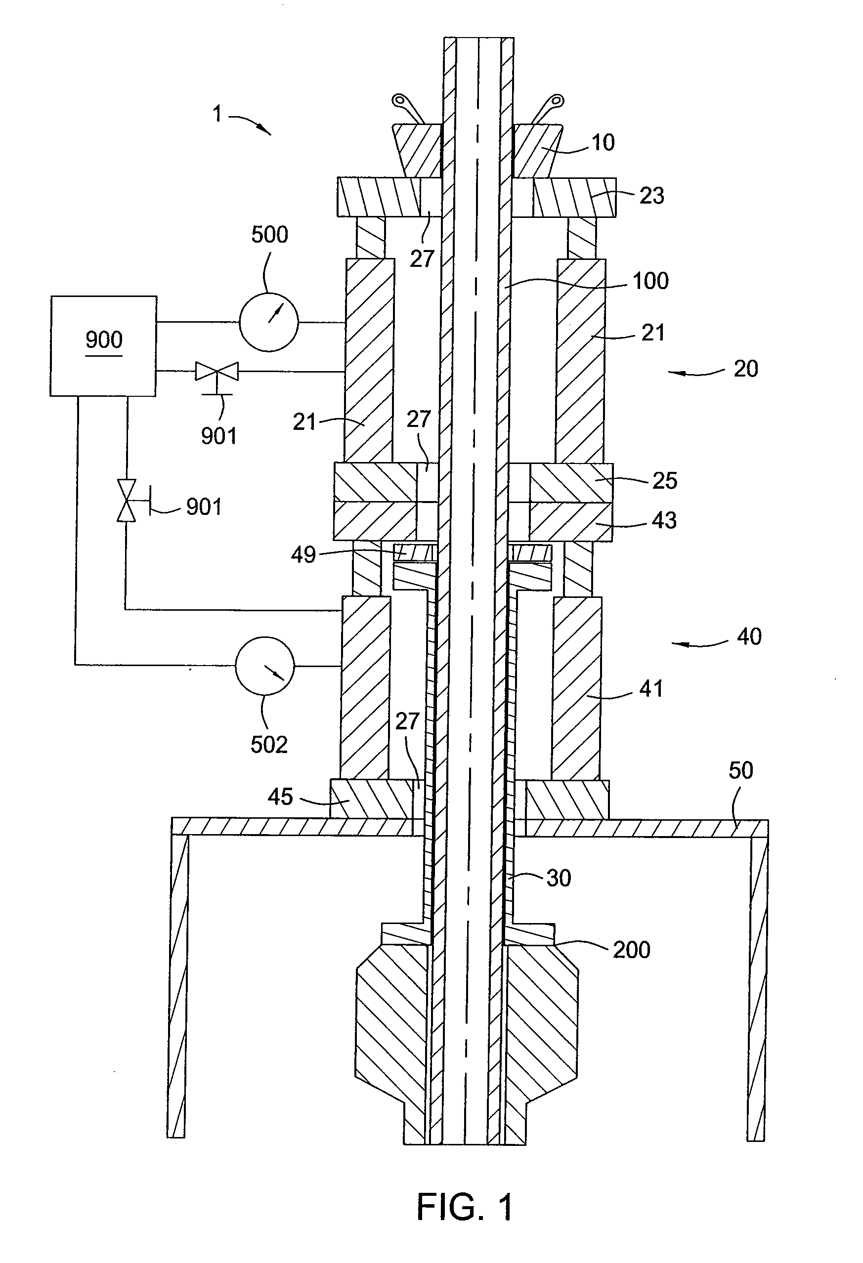
[0018]FIG. 1 illustrates a cross sectional elevation view of a tubular 100 attached to a lifting apparatus 1. The tubular 100 is any tubular for use in downhole wellbores such as, but not limited to, casing, liner, drill string, coiled tubing, and production piping. The lifting apparatus 1 includes a gripping member 10 for gripping the tubular 100. As shown, the gripping member 10 is a spider type gripper such as that disclosed in U.S. Publication No. 2004 / 0251055 A1, which is herein incorporated by reference; however, it should be appreciated that the gripping member 10 may be any type known in the art such as a spear, as disclosed in U.S. Publication No. 2005 / 0051343 A1, which is herein incorporated by reference, or any other device adapted to grip tubulars. The gripping member 10 attaches to a lifting member 20.

[0019] The lifting member 20, as shown, comprises a hydraulic jacking system with one or more fluid operated cylinders 21 attached to a top plate 23 and a bottom plate 25...


PUM


Abstract

A method and apparatus for removing tubulars from a wellbore is disclosed. A lifting member grips the tubular and applies a lifting force. The lifting force is then transferred to a first surface. The lifting member is monitored and when the capacity of the first surface is reached a force transfer assembly is activated. The force transfer assembly transfers the lifting load between the first surface and a second surface. The lifting member and force transfer assembly are then adjusted to maximize the amount of lifting force applied to the tubular.

Description

CROSS-REFERENCE TO RELATED APPLICATIONS [0001] This application claims benefit of U.S. provisional patent application Ser. No. 60 / 726,946, filed Oct. 14, 2006, which is here incorporated by reference.BACKGROUND OF THE INVENTION [0002] 1. Field of the Invention [0003] Embodiments of the present invention generally relate to a method and apparatus for removing tubulars from a wellbore. Particularly, the present invention relates to a method and apparatus for increasing the amount of lifting force applied to a wellbore tubular when removing the tubular from the ground. More particularly still, the present invention relates to a method and apparatus for distributing the lifting force between two separate load surfaces for an increased lifting force. More particularly still, the present invention relates to controlling and monitoring a lifting force between two separate load surfaces. [0004] 2. Description of the Related Art [0005] In the operation of oil and gas wells, it is common to r...

Claims


Application Information

Patent Timeline
Patent Type & Authority Applications(United States)
IPC IPC(8): E21B23/00
CPCE21B19/086E21B19/02
Inventor HALLONQUIST, DAVID J.MAYER, TIMOTHY J.
Owner WEATHERFORD TECH HLDG LLC
Why Eureka
Try Eureka