

Internal combustion engine, and control apparatus and method thereof
- Summary
- Abstract
- Description
- Claims
- Application Information
AI Technical Summary
Benefits of technology
Problems solved by technology
Method used
Image

Examples
Embodiment Construction
[0043] Embodiments of the present invention will be described below with reference to the drawings.
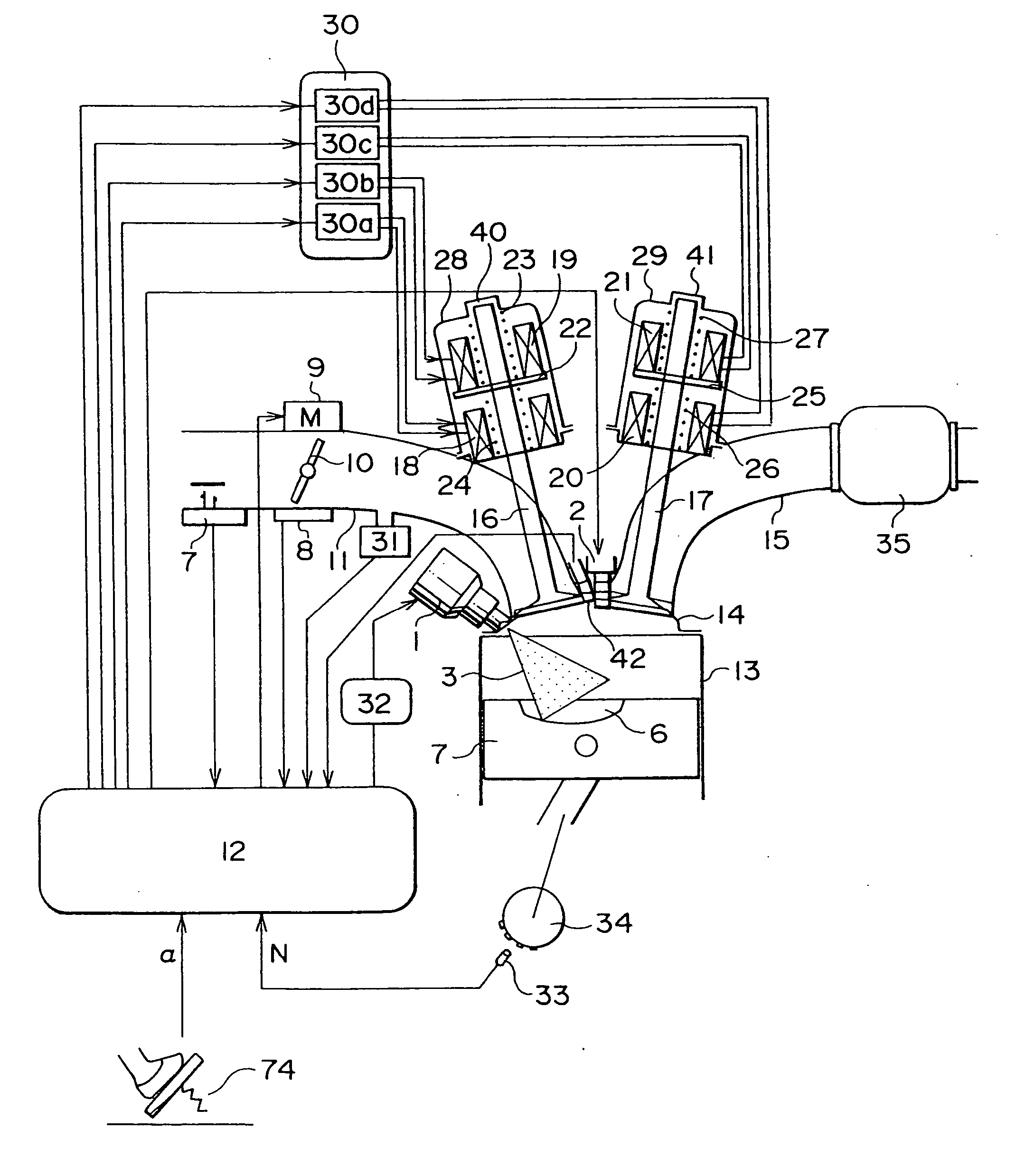
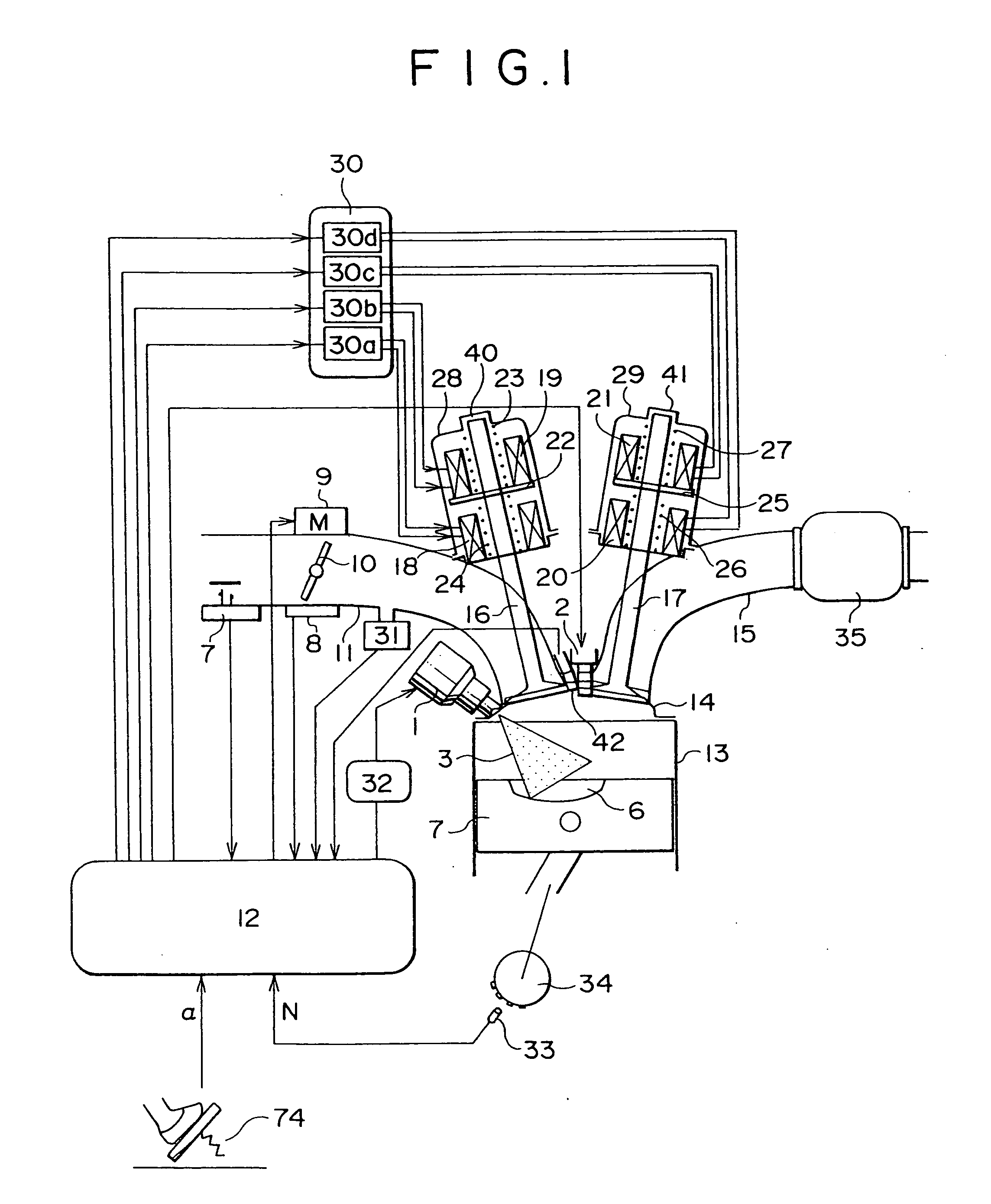
[0044]FIG. 1 illustrates a configuration of the present invention. Air is introduced into an engine 13 through an air flow sensor 7, a throttle valve 10, a branch pipe 11, and an intake valve 16 in each cylinder. The amount of air can be controlled by changing the degree of opening of the throttle valve 10 and that of the intake valve 16 and it is metered by the air flow sensor 7. Where required, an internal pressure of an intake pipe and that of each cylinder are detected by means of an internal intake pipe pressure sensor 31 and an internal cylinder pressure sensor 42, respectively. As to the intake valve 16, a movable portion 22 operates under the action of an electromagnetic force induced by applying a voltage to electromagnetic solenoids 18 and 19 through a drive circuit 30, and the intake valve 16, which is connected to the movable portion 22, operates in its opening or closing ...
PUM
 Abstract
Description
Claims
Application Information