Interlocking clamp

a clamp and clamping technology, applied in the field of clamping clamps, can solve the problems achieve the effects of increasing setup time, and reducing the number of clamping parts

Active Publication Date: 2016-01-26
ROYAL JEREMY PATRICK
View PDF3 Cites 0 Cited by
  • Summary
  • Abstract
  • Description
  • Claims
  • Application Information

AI Technical Summary

Benefits of technology

[0012]This invention comprises an improvement to bar and c-clamps to allow them to be temporarily coupled in such a way as to render them fixed at specified angles to each other in a plane perpendicular to that of the workpiece. This allows the assembly of temporary clamping fixtures (jigs) from multiple clamps, allowing more precise control of workpiece and joint geometry. Rather than using external tools or other measures to control this geometry, the alignment hardware is largely internal to clamps equipped with this invention, allowing greater simplicity of clamp hardware. An angle of the jaws of the clamps is fixed by one or more of the following: lugs on the clamp heads and feet, a fixed profile hole in the clamp heads and feet, bar stock connecting selected clamp heads and feet, and a locking mechanism in the clamp heads and feet that applies force to the connecting bar stock.
[0013]The invention does not require use of threaded components to connect clamps. Using threaded components to maintain distance between clamps can greatly increase setup time, particularly for larger arrangements of clamps and connecting parts. The invention uses for this purpose unthreaded metal bar stock, which is more easily obtained than custom components. As the length of the bar stock need not be tailored to a given jig or arrangement of clamps, setup is easier than with threaded rod or other components that require cutting before use.
[0014]Clamps designed with this invention may be used as basic bar or c-clamps, fulfilling the same uses of non-modified clamps with no loss of function and a minimal loss of rigidity.

Problems solved by technology

Using threaded components to maintain distance between clamps can greatly increase setup time, particularly for larger arrangements of clamps and connecting parts.

Method used


Image

  • Interlocking clamp
  • Interlocking clamp
  • Interlocking clamp

Examples


Embodiment Construction

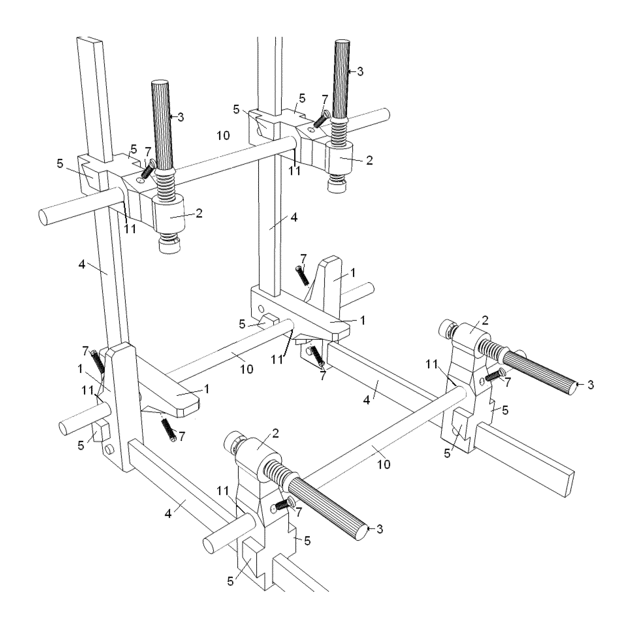
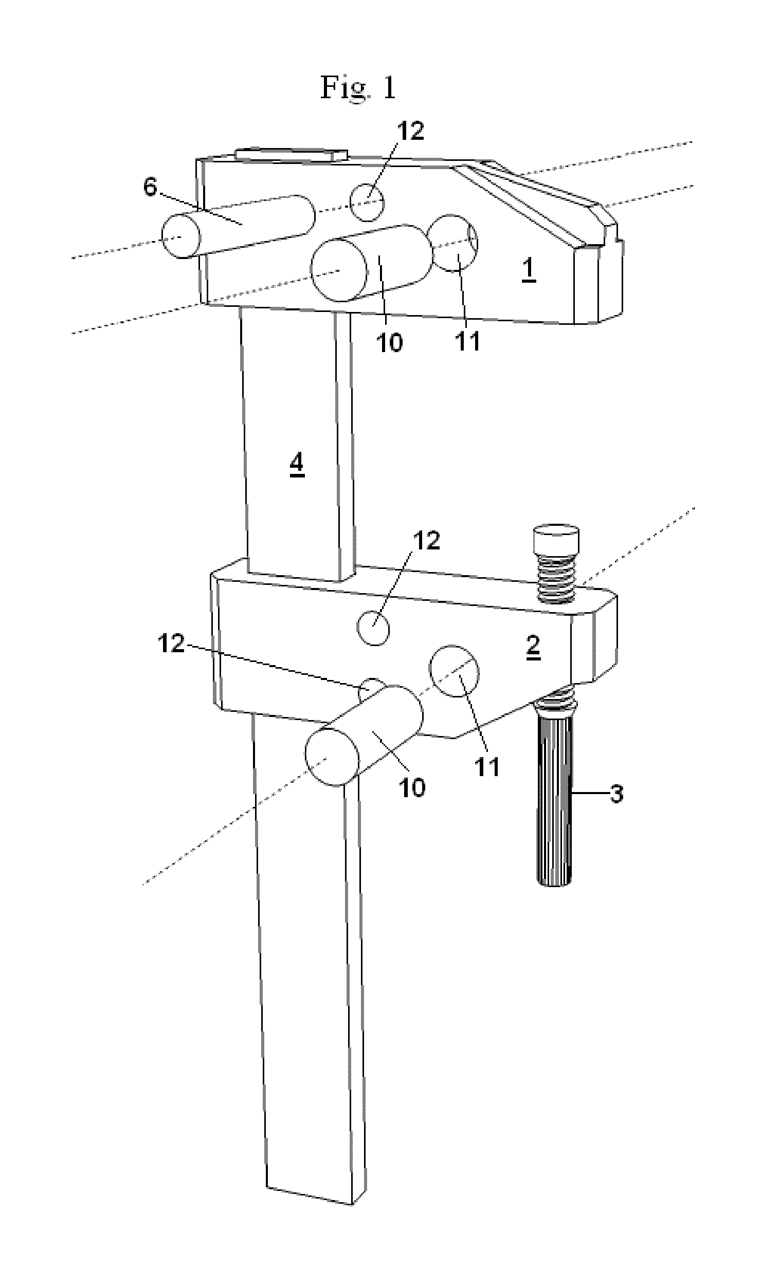
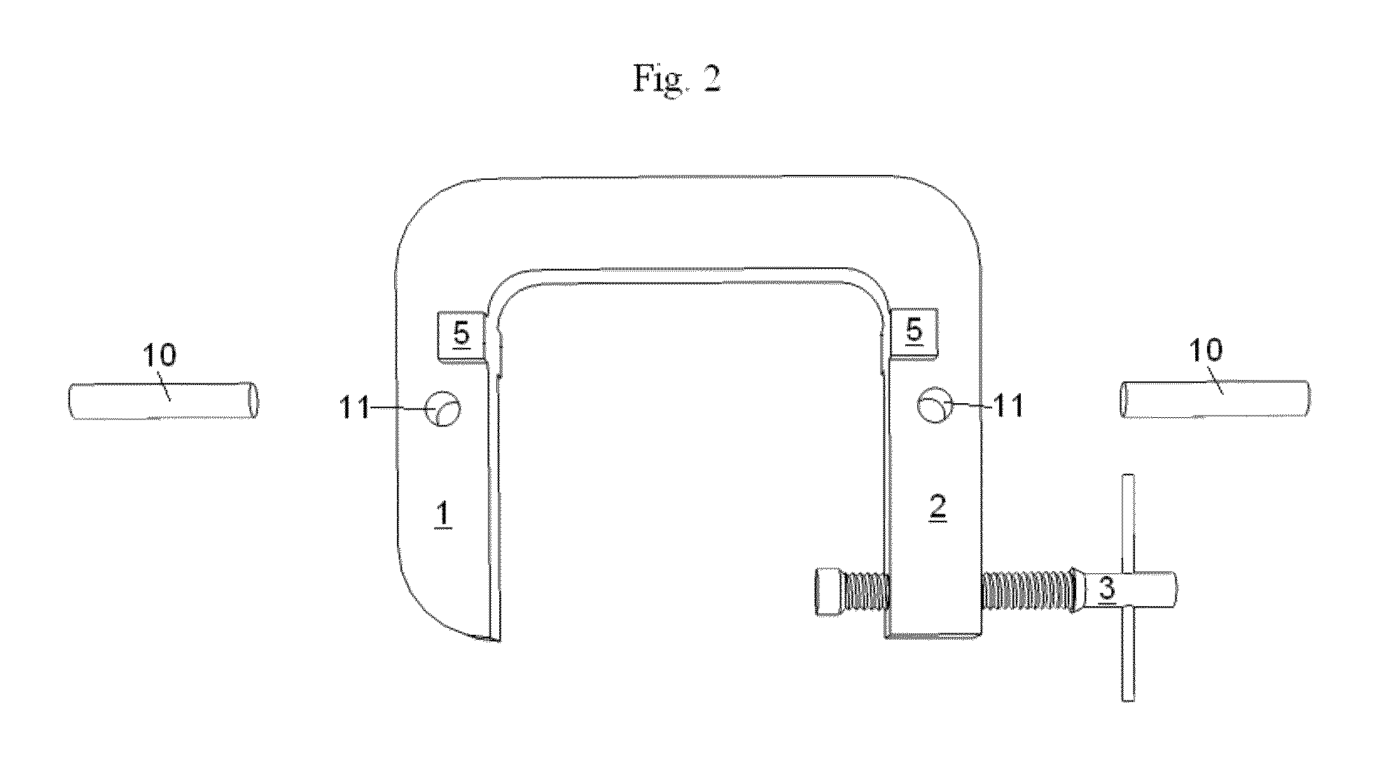
[0024]This invention consists of several improvements to of bar and c-clamps, allowing them to connect to each other in such a way as to fix the geometry between clamps. Both bar and c-clamps have a head and a foot between which one or more workpieces are clamped. It is to and between these parts of the clamps that this invention is applied. As such, the invention can be used to improve many of the numerous types of bar and c-clamps, whose previous various innovations are primarily concerned with locking mechanisms used to immobilize the head and foot relative to each other along the clamping axis.

[0025]Referring to FIG. 1, the basic elements of an F-type bar clamp include 1 the head of the clamp, 2 the foot of the clamp, 3 a tensioning mechanism that permits the exertion of a compressive force perpendicular to the head 1 and foot 2 of the clamp, in this example a screw and handle, and 4, a bar or connecting structure along which one or both of the head and foot may move. Commonly i...


PUM


Abstract

The present invention allows multiple bar or c-clamps to be connected by one or more bars, the bars passing through the head and / or feet of the clamps, with provisions for locking the angles of the clamps about the bars joining them. This allows temporary jigs to be quickly assembled, with the angles of the workpieces held by the clamps to be fixed relative to one another at specified angles. In addition, parallelism of clamps holding a single workpiece may be maintained through the use of two or more connecting bars.

Description

REFERENCE TO RELATED APPLICATIONS[0001]Not ApplicableACKNOWLEDGMENT OF GOVERNMENT SUPPORT[0002]Not ApplicableMICROFICHE APPENDIX[0003]Not ApplicableBACKGROUND OF THE INVENTION[0004]1. Field of the Invention[0005]The invention pertains to the field of bar and c-clamp type tools used for holding two or more workpieces at fixed angles to each other. More particularly, the invention pertains to an improvement to clamps to allow two or more clamps to be joined at fixed angles to each other while they hold a workpiece or workpieces.[0006]2. Description of Related Art[0007]Bar clamps, C-clamps, and related tools, typically exert their force along one line. While much prior art has been devoted to immobilization of workpieces and clamps relative to the plane of the workpieces, there has been little work done in joining bar or c-clamps rigidly in a manner that allows them to exert force on a joint along multiple lines. Clamping at right angles to another bar clamp is usually done with the ge...

Claims


Application Information

Patent Timeline
Patent Type & Authority Patents(United States)
IPC IPC(8): B25B5/00B25B5/10B25B11/00B25B11/02
CPCB25B5/003B25B5/102B25B11/00B25B11/02
Inventor ROYAL, JEREMY, PATRICK
Owner ROYAL JEREMY PATRICK
Why Eureka
Try Eureka